Resolved! NUCLEO-C5A3ZG STM32C5 QSPI Display Bring up Project
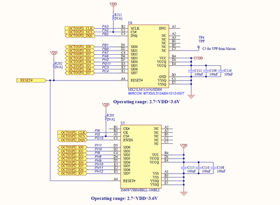
This project tests the STM32C5's XSPI capability to drive QSPI display using the NUCLEO-C5A3ZG M.2/SerialMem connector. GitHub - stm32-hotspot/STM32C5-M2-Serial-Mem-QSPI-Display · GitHub

Ask questions and find answers on STM32 hardware set-ups, including schematic-related challenges, debugging probes, power configurations, and more.
This project tests the STM32C5's XSPI capability to drive QSPI display using the NUCLEO-C5A3ZG M.2/SerialMem connector. GitHub - stm32-hotspot/STM32C5-M2-Serial-Mem-QSPI-Display · GitHub
Hello,I received my STM32F446ret6-based PCB for my student project, PCB was already assembled from the JLCPCB factory and I can't program it through the SWD header with ST-link. I checked every trace on PCB with schematic and measured continuity with...
When I try to debug the standard led toggle example I get the No ST-LINK detected message,Board: STM32H7A3ZIT6QHost: Windows 11IDE: STM32CubeIDE 1.10.1When I open Device Manager and connect the board to USB there is not one extra device detected. I a...
In the picture:pin 1 top left: VDD 3.3V 4 100n to GRND 14 to GRND 15 to VDD 16 to GRNDon their left 1µ and 10n F decoupling VDDA VSSApin 32 top right : VSS 0V GRNDpin 31 10K ohm to GRND 24 SWD clk 23 SWD dio 17 to GRN...
Hello STM enthusiasts,I am reaching out as I am having a puzzling issue with connecting to my STM32 chip with an ST-LINK V2.What I have for a set up is:OS: Windows 10 x64 bitIDE: Atollic TrueStudio v9.1.0Debugger/Programmer: ST-LINK V2Chip: STM32F030...
Can anyone please let me know, how is this possible?
I have got a custom PCB using STM32F4. I don't have any capacitor connected to the VCAP Pin and I wonder if this is necessary or not. Which is the use of VCAP and do I need to add it to my design? What can I do to solve my problem of no having one if...
For a long time I have been using the following setup:two STM32H7 eval boardsone gdbserver session for each STM32, with a different portremote debugging on the two STM32I just switched from STM32CubeIDE 1.0 to 1.10.1 and now I have this weird behavio...

I have two devices I am looking to integrate with STM32 MCPUs. One is a Honeywell HG1125 IMU and the other is an WFF93 Encoder.Both devices use LVDS signalling. I don't know much about that signaling at this point, but I am taking a broad stroke fi...
I see from the schematics in datasheet UM1956 that there is a reserved CN2 connector with SWDIO and SWCLK, NRST can be found on CN3. But I do not see any jumpers to switch whether ST-LINK is used to program on-board Nucleo MCU or an external MCU like...
We’re moving the ST Community to a new platform to give you a better and more reliable community experience.
