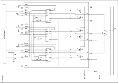
Connection of STGIPS20K60
HelloCould someone please help me with information on how to define the values of the capacitors and resistors seen in the figure of the typical circuit? Thanks
Discuss power management solutions. Ask questions and find answers on voltage configurations, short circuit protection, and programming.
HelloCould someone please help me with information on how to define the values of the capacitors and resistors seen in the figure of the typical circuit? Thanks
Hello,I was wondering why a 1K resistor is connected in series with the VSPI pin of the EV-VNF1048F.The pin has a current consumption of 3mA. So does that make a drop of 3V ?
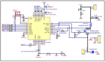
Hello,I was checking the evaluvation board of VNF1048F for a efuse application to control motor drive. I wish to know how the capcitors for the charge pump selected in the evaluvation board. I am able to see 470nF in the evaluvation board schematics....
We are using the PowerSTEP01 driver in Current mode to drive the NEMA23 stepper motor.Supply voltage: 24V DC, Motor current 0.9A set in driver (motor max current is 2.1A)RPM Range 0 -1800 rpm; (0 - 6500 steps/sec)Acceleration / deceleration = 10000 ...
I've been working with the MASTERGAN4L dev board to drive a transformer. This is for a purpose that will have to survive travel through deep space. I have a discretized roughly equivalent circuit made out of explicitly radiation tolerant / space rate...
Hi,I am working with this driver for a full H-Bridge inverter application (DC-AC). My requirements exceed the current rating for the SiC MOSFETs I am using. I am planning on paralleling MOSFETs to meet the current requirements, so I would like to kno...
I am designing a 200W 36V supply with STCMB1 driver, I am having problems with the circuit. The supply cannot supply the 6A of its capacity, it does not supply more than 800mA and the output voltage drops to 33V.
Hello, We plan to use the STWLC38 for power in a new wearable design. We purchased the STEVAL-WLC38RX and STEVAL-WBC86TX kits to get familiar and experiment with the ICs. Now we are trying to adapt the Rx of the STEVAL-WLC38RX as used in a wearable d...
We've developed prototype board with 3 pcs AL1262ZT (https://www.st.com/en/power-management/aled1262zt.html). As a 'fresh device' it has 0x40 I2C address and it's need to specify unique addr (0x42, 0x44, 0x46) by burn OTP register. Our procedure: 1. ...
We use wireless charger RX IC stwlc38, though we tried to write firmware which provided by the link https://github.com/STwirelesscharger/STWLC38_NUCLEO_L476RG, but we met the CUT id mismatch during firmware writing via I2C interface and then the F/W ...

