Power management
Discuss power management solutions. Ask questions and find answers on voltage configurations, short circuit protection, and programming.
Turn on suggestions
Auto-suggest helps you quickly narrow down your search results by suggesting possible matches as you type.
Showing results for
- STMicroelectronics Community
- Product forums
- Power management
Options
- Mark all as New
- Mark all as Read
- Float this item to the top
- Subscribe
- Bookmark
- Subscribe to RSS Feed
- Invite a Friend
- Threaded format
- Linear Format
- Sort by Topic Start Date
Forum Posts
B-g431b-esc1 vs steval-esc001v1
Hello all, I would like to understand the key differences between the two controllers and which one would better suit my needs. I want to precisely control the speed of two sensorless bldc motors, keeping them in sync regardless of the load each of ...
Resolved! Using STEF01 as a high-side switch
Hi,I'm planning to use STEF01 as a high-side switch plus an external MOSFET for blocking inverse current from load. Is this feasible or I would be wrong?gaston
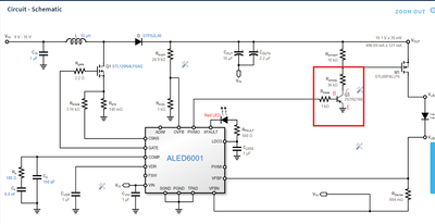
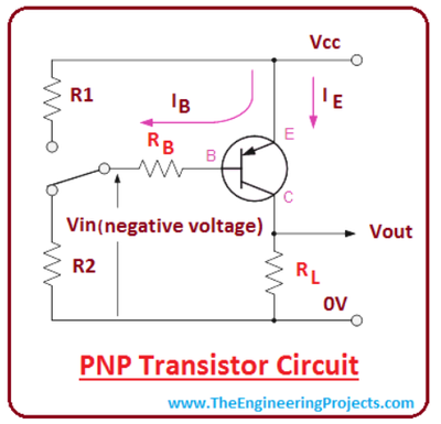
Resolved! ALED6001 eDesign dimming setting
Hi Sir,ALED6001 eDesign show BJT is as the red rectangle.However, most PNP BJT is show as below picture.I search some data, they show exchanging BJT's E and C, BJT can work. However, the hfe will decrease and the BJT cannot afford high voltage.Below...
Energy Harvester SPV1050 / STEVAL-ISV019V1: When connecting > 4-6uF on the LDO output, the LDO voltage collapses
I'm currently prototyping with the Steval-ISV019V1 (evaluation board for SPV1050) and have only changed the resistor ladder for MPPT. Energy harvesting works nice.But when I enable one of the LDOs and have > 4-6uF connected on the LDO output, the LD...
Resolved! L6482 step-clock mode
Hello,I am designing a stepper motor controller with L6482.The choice of L6482 was made because of its integrated dual h-bridge gate drivers and relatively high voltage rating.The chip features nice set of motion commands but due to specific demands ...
-
Motor Control Hardware
2,423 -
Power Supply Management
547 -
DC-DC Conversion
450 -
AC-DC Conversion
330 -
Battery Management
248 -
Automotive Power
211 -
Discretes
167 -
Wireless charging
109 -
Intelligent Power Switches
108 -
Lighting And LED
83 -
Gate drivers
22 -
STWLC38
21 -
STWBC86
20 -
SPI
16 -
Power
16 -
TIM
12 -
STM32MP15 lines
12 -
USB-PD
11 -
STM32F4 Series
9 -
Bug-report
8 -
STM32F1 Series
8 -
STM32G4 Series
6 -
Documentation
5 -
ADC
5 -
Galvanic isolation
4 -
ST boards
4 -
I2C
4 -
eDesignSuite
4 -
UART-USART
4 -
Other hardware
4 -
Other boards
3 -
ST-Link
3 -
USB
3 -
STM32G0 series
3 -
TCPP
3 -
Need clarification
2 -
USB Type-C and Power Delivery
2 -
SW4STM32
2 -
RESET
2 -
STM32duino
2 -
Other software
2 -
Keil
2 -
ST-Boards
2 -
STM32 Motor Control
2 -
RCC
2 -
STM32L0 Series
2 -
STM32L4 series
2 -
Interrupt
1 -
Schematic
1 -
TouchGFX
1 -
Power Line Communication
1 -
Gerber
1 -
Power management Design center
1 -
BMS
1 -
STM32F0 Series
1 -
STM32F3 Series
1 -
CAN
1 -
simulators
1 -
Low Power RF Solutions
1 -
BLE
1 -
STM32CubeIDE
1 -
Discontinued products
1 -
Simulators (TwisterSim - ST PowerStudio - AC Switch - Diodes)
1 -
Suggestion
1 -
Current sensing
1 -
Switches and multiplexers
1 -
IWDG-WWDG
1 -
LCD-LTDC
1 -
DAC
1 -
Mbed
1 -
OPAMP
1 -
Modbus
1 -
DFSDM
1 -
Legacy products
1

