Turn on suggestions
Auto-suggest helps you quickly narrow down your search results by suggesting possible matches as you type.
Showing results for
- STMicroelectronics Community
- STM32 MCUs
- STM32 MCUs products
- Weird (for me) problem(s) with ADC and DMA on STM3...
Options
- Subscribe to RSS Feed
- Mark Topic as New
- Mark Topic as Read
- Float this Topic for Current User
- Bookmark
- Subscribe
- Mute
- Printer Friendly Page
Weird (for me) problem(s) with ADC and DMA on STM32F3348
Options
- Mark as New
- Bookmark
- Subscribe
- Mute
- Subscribe to RSS Feed
- Permalink
- Email to a Friend
- Report Inappropriate Content
2020-06-19 10:04 AM
First, I have done this before successfully on the STM32F446re with all 3 ADCs and DMAs but I need some guidance or ideas... STM32F3348 Disco OR my target PCB with same processor. ADC1 (and maybe ADC2) using DMA to convert 7 channels on ADC1 and 4 channels on ADC2 and place them in the arrays. Regular sequence (not injected, etc). It's easier to sit in the easy chair and use the Disco board... I have done another project on the STM32F446Re with similar setup with 3 ADCs and DMA and it works perfectly so this one is really weird. This 3348 processor appears to use DMA in a slightly different way though. For instance, channels instead of streams etc.
I DO get ADC results on both targets and the correct amount of array fills (7 and 4 locations). Using IAR EWARM 6.5 and ST-Link.
One thing that appears to be going wrong is that for ADC1 anyway, every time I stop the debugging, the order of the A2D results appear to be shifted in the array. I can't tell which one is correct either. One of the ADC1 channels is looking at the internal temp sensor and I was able to see that it does change with temperature but things do not stay put in their same spots in the array. But as far as I can tell, the values are spaced correctly. But there are more weird issues. Sometimes when hitting F5 to "GO" and then stop, I don't get any numbers changing but usually do. And it WAS that I had to read the ADC1->DR register or it would NOT run more than a couple of times, I think, due to the OVR flag being set. When I would go off of looking at ADC1_2 registers (ADC1 and common ADC regs I think that is for) it would stop running. Then I put a line in code in main() to just read the DR register and it kept ADC1 running. Very strange. I do not have any interrupts set to go for ADC or DMA. Same with my other STM32F446re project which works.
ADC2 appears to work but it may be having the same issue of not putting conversion results in the right places but the numbers are so close to each other it is hard to tell.
This is really strange. Hardware appears to run great otherwise.
Any ideas to troubleshoot this ?
Much appreciated !
PS. Both ADC and DMA have the same number for sequence and NDT respectively... i.e. number of conversions and transfers are both 7 for ADC1 and CH1 of DMA1 and both 4 for ADC2 and DMA1 channel 2. I had hoped it was just something stupid like that.
Attaching some captures of the debug registers to help illustrate some conditions.
First pic (AD1.png) is of watch registers on the right side showing one run-stop of debugging. Notice the numbers in ADC1DMA[] array and then a pic of another run-stop with very similar ADC1 conversion numbers but in a different spot. In this debug capture, I had to be watching the ADC1_2 registers. What ADC1_2 is is evidently the ADC1 registers AND the ADC1 and ADC2 COMMON registers. I am running these two ADCs in independent mode and not linked or synced together.
AD2.png is another run-stop of the debugging. You can also see some of the ADC1 registers on the left side as well as some of the hadc1 handle settings for ADC1. Notice how the ADC1DMA array values are shifted here.
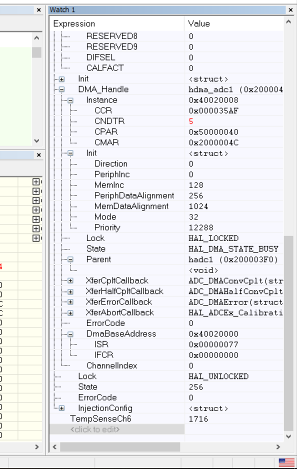
Next is a pic of DMA register capture on the right including some of the DMA1 registers on the left in yellow as they were when I stopped the debugging...
And one more pic of the DMA1 HAL handle register values because they don't all fit on one screen.
Thanks for having a look guys !
boB
Solved! Go to Solution.
Labels:
- Labels:
-
ADC
-
DMA
-
STM32F3 Series
1 ACCEPTED SOLUTION
Accepted Solutions
Options
- Mark as New
- Bookmark
- Subscribe
- Mute
- Subscribe to RSS Feed
- Permalink
- Email to a Friend
- Report Inappropriate Content
2020-07-05 11:17 PM
Figured it out.
Thank you to Eddie's STM32 videos for pointing out to me that the L[3:0] number if sequences to go through with a value of 0000 really means 1 (one) conversion !!!!
https://youtu.be/8lmujnLuJrQ?t=352
I had mistakenly thought that setting L[3:0] to 7 meant to sequence 7 registers and so it did NOT match the number of transfers programmed into DMA1 channel 1 and so that was why my DMA1 output array of ADC1 values did NOT appear in the same positions all the time. Reducing L[3:0] to 6 fixes this problem.
I may have had some OVR overrun errors but playing with that with IRQs did not help.
8 REPLIES 8
Options
- Mark as New
- Bookmark
- Subscribe
- Mute
- Subscribe to RSS Feed
- Permalink
- Email to a Friend
- Report Inappropriate Content
2020-06-19 10:31 AM
The overrun flag is set, i.e. DMA can't pick data fast enough.
JW
Options
- Mark as New
- Bookmark
- Subscribe
- Mute
- Subscribe to RSS Feed
- Permalink
- Email to a Friend
- Report Inappropriate Content
2020-06-19 11:11 AM
Thank you Jan. I saw that. I made the prescaler big but that didn't help.
I may be able to go one slower though. I can also try the much larger conversion cycle time which is quite a bit slower.
Will report back.
I also wish the OVRMOD setting worked in this mode.
Options
- Mark as New
- Bookmark
- Subscribe
- Mute
- Subscribe to RSS Feed
- Permalink
- Email to a Friend
- Report Inappropriate Content
2020-06-19 04:32 PM
Slowing down will not solve the problem. First, when some other interrupt or whatever code delays the ADC servicing for some longer time, you need the system to recover and continue functioning correctly. Second, when stopped in debugging, you will always get an overrun. The solution is rather simple. Enable the overrun interrupt and, when it happens, disable DMA channel, reinitialize the number of data to transfer, enable DMA channel and clear the overrun flag.
Options
- Mark as New
- Bookmark
- Subscribe
- Mute
- Subscribe to RSS Feed
- Permalink
- Email to a Friend
- Report Inappropriate Content
2020-06-20 12:02 AM
Thank you Piranha. I will try an OVRIE method.
I find it interesting though that with my STM32F446re project that uses a LOT more DMA (3X ADC, Tim1,Tim8, TIm2 DMA etc) as well as a 200 microsecond interrupt, that it does not hiccup at all it seems with the ADCs. Now, it IS running at 180MHz instead of a measly 72 MHz like the 334 but still... That is weird.
I will post back if OVR interrupt handling helps. My next thing was to do something like that anyway but I must do it now.
Thanks again guys. If you come up with any other ideas, I'm all ears !
boB
Options
- Mark as New
- Bookmark
- Subscribe
- Mute
- Subscribe to RSS Feed
- Permalink
- Email to a Friend
- Report Inappropriate Content
2020-07-01 08:41 PM
Well, I don't want to give up but I am still not getting this to work correctly at least for ADC1.
I did what Piranha said to do, I think, and still, the results move around.
I am converting 7 values from ADC1 and 7 values are being distributed to the array of registers.
I have an ADC1 OVR interrupt and it occurs approximately once every 3 milliseconds.
How can I set or reset the SEQ sequence of regular A/D conversions in the ADC ? And how can I tell the DMA1 CCR1 where to be pointing at ?
This was much easier in the F446 part. These peripherals work differently. I get NO overflows on that processor and I am using about the same number of ADC channels.
Any other ideas ? I don't really want to use an interrupt EOC interrupt but I may have no choice ?
Thanks
Options
- Mark as New
- Bookmark
- Subscribe
- Mute
- Subscribe to RSS Feed
- Permalink
- Email to a Friend
- Report Inappropriate Content
2020-07-05 11:17 PM
Figured it out.
Thank you to Eddie's STM32 videos for pointing out to me that the L[3:0] number if sequences to go through with a value of 0000 really means 1 (one) conversion !!!!
https://youtu.be/8lmujnLuJrQ?t=352
I had mistakenly thought that setting L[3:0] to 7 meant to sequence 7 registers and so it did NOT match the number of transfers programmed into DMA1 channel 1 and so that was why my DMA1 output array of ADC1 values did NOT appear in the same positions all the time. Reducing L[3:0] to 6 fixes this problem.
I may have had some OVR overrun errors but playing with that with IRQs did not help.
Options
- Mark as New
- Bookmark
- Subscribe
- Mute
- Subscribe to RSS Feed
- Permalink
- Email to a Friend
- Report Inappropriate Content
2020-07-06 12:29 PM
Good - mark your post as an answer. 🙂 But keep in mind that what was said about overrun is still relevant!
Options
- Mark as New
- Bookmark
- Subscribe
- Mute
- Subscribe to RSS Feed
- Permalink
- Email to a Friend
- Report Inappropriate Content
2020-07-06 12:34 PM
I will be keeping the OVR IRQ but still not sure how to implement it properly.
Wish there was an exact sample for that but there are so many possibilities that I don't think there will be one.
This is hard stuff sometimes !
Related Content
- STM32H730: Enabling caching on OCTOSPI RAM crashes the program in STM32 MCUs products
- Question regarding linker sections and behaviour in STM32 MCUs Embedded software
- X-Cube-AI Not generating application for F302R8 but works for G070RB in STM32CubeIDE (MCUs)
- R/W SPI with STM32H743 in STM32 MCUs Embedded software
- How to set up IRAM1/IRAM2 in Keil with STM32H742VIT6? in STM32 MCUs products