Turn on suggestions
Auto-suggest helps you quickly narrow down your search results by suggesting possible matches as you type.
Showing results for
- STMicroelectronics Community
- STM32 MCUs
- STM32 MCUs Boards and hardware tools
- Re: STM32H743XIH6 Crystal Frequency
Options
- Subscribe to RSS Feed
- Mark Topic as New
- Mark Topic as Read
- Float this Topic for Current User
- Bookmark
- Subscribe
- Mute
- Printer Friendly Page
STM32H743XIH6 Crystal Frequency
Options
- Mark as New
- Bookmark
- Subscribe
- Mute
- Subscribe to RSS Feed
- Permalink
- Email to a Friend
- Report Inappropriate Content
2024-02-08 04:44 AM
Hi ST Support Team,
I am Using STM32H743XIH6 in one of the project.
Having Query related to crystal frequency.
In datasheet frequency characteristics is provided for oscillator input.
In my Design and STM32H743XIH6 Evaluation Board crystal is implemented.
My Design contains 48Mhz Crystal while EVM contains 25Mhz crystal.
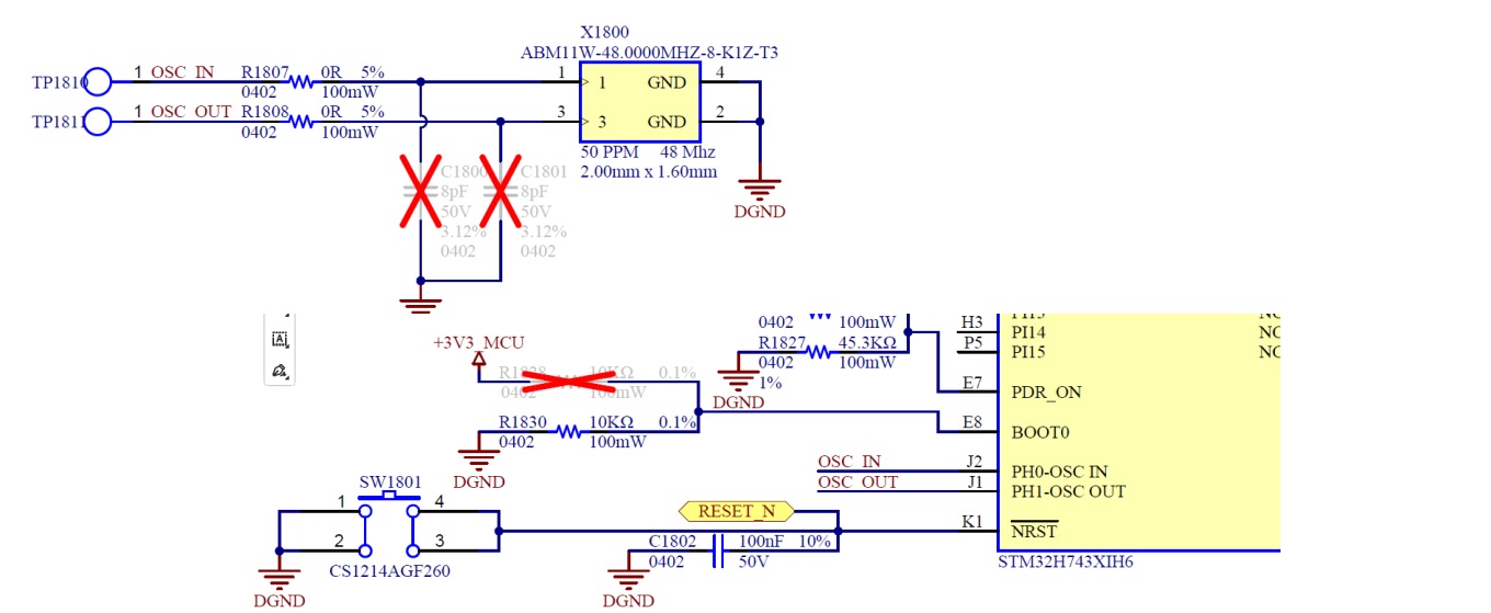
Kindly go through the attached schematic capture of developed board waveform capture at PH0-OSC_IN pin.
Getting same waveform as per Evaluation Kit (Find Attached EVM waveform)
Hope waveform we observed will specify the MCU clock requirement in terms of rise time, fall time, VIH & VIL level.
want to make sure that there is no issue in MCU Clock using external 48 Mhz crystal implementation.
in 25 Mhz & 48 Mhz crystal maximum amplitude is going at 1.8V and MCU operating at 3.3V level.
Hoping that the clock at OSC_PIN is satisfying MCU operating level.
Thanks,
Labels:
- Labels:
-
STM32H7 Series
14 REPLIES 14
Options
- Mark as New
- Bookmark
- Subscribe
- Mute
- Subscribe to RSS Feed
- Permalink
- Email to a Friend
- Report Inappropriate Content
2024-02-08 04:54 AM
Check the datasheet, for H733 its is:
6.3.9 External clock source characteristics
High-speed external user clock generated from an external source
fHSE_ext User external clock source frequency max 50 MHz
Options
- Mark as New
- Bookmark
- Subscribe
- Mute
- Subscribe to RSS Feed
- Permalink
- Email to a Friend
- Report Inappropriate Content
2024-02-08 05:09 AM
Hi LCE,
After Referring the H733, 6.3.9.
Found, maximum Low Level of Clock need to be 0.3*VDD (= 0.7*3.3 = 0.99), in my case & in EVM it is ~1.2V
For Minimum High Level of clock need to be 0.7*VDD (= 0.7 *3.3 = 2.31), in my case & in EVM it is ~1.8V.
So considering datasheet parameter for both board not maintaining required level, correct?
Can you help me to get resolution on above concern?
Thanks..
Options
- Mark as New
- Bookmark
- Subscribe
- Mute
- Subscribe to RSS Feed
- Permalink
- Email to a Friend
- Report Inappropriate Content
2024-02-08 05:12 AM
Max external crystal frequency is 48 MHz, which yours meets. You should have load capacitors loaded.

The waveform looks fine.
See here for crystal selection design guide:
If you feel a post has answered your question, please click "Accept as Solution".
Options
- Mark as New
- Bookmark
- Subscribe
- Mute
- Subscribe to RSS Feed
- Permalink
- Email to a Friend
- Report Inappropriate Content
2024-02-08 05:29 AM
Options
- Mark as New
- Bookmark
- Subscribe
- Mute
- Subscribe to RSS Feed
- Permalink
- Email to a Friend
- Report Inappropriate Content
2024-02-08 05:32 AM
Hi
Find attached snap, ignore previous one..
Thanks,

Options
- Mark as New
- Bookmark
- Subscribe
- Mute
- Subscribe to RSS Feed
- Permalink
- Email to a Friend
- Report Inappropriate Content
2024-02-08 06:29 AM
I imagine the capacitance of your scope is distorting things as well.
> Crystal having 8 pF load capacitance, added 8 pF capacitor at both pins and getting same result as without load capacitance.
Just because it works doesn't mean it will continue to do so. Follow the recommendations to have the best chance of success. A little surprised it's working at all without any load caps.
Don't mix up specifications for the external clock input with specifications for the external crystal.
If you feel a post has answered your question, please click "Accept as Solution".
Options
- Mark as New
- Bookmark
- Subscribe
- Mute
- Subscribe to RSS Feed
- Permalink
- Email to a Friend
- Report Inappropriate Content
2024-02-08 06:34 AM
Hi TDK,
We kept Load Capacitance Open due to STM32 10pF Load capacitance.
STM32 Capacitance matching Load capacitance requirement for crystal.
Thanks,
Options
- Mark as New
- Bookmark
- Subscribe
- Mute
- Subscribe to RSS Feed
- Permalink
- Email to a Friend
- Report Inappropriate Content
2024-02-08 08:51 AM
> STM32 10pF Load capacitance.
Where are you getting this from?
The required load caps on a CL=8pF crystal should be about 2 * 8 pF - 6 pF = 10pF.
If you feel a post has answered your question, please click "Accept as Solution".
Options
- Mark as New
- Bookmark
- Subscribe
- Mute
- Subscribe to RSS Feed
- Permalink
- Email to a Friend
- Report Inappropriate Content
2024-02-08 07:40 PM
Hi TDK,
Referring to attached snap considering STM32 10pF load capacitance.

Thanks,
Related Content
- STM32F417VGT VCAP Voltage Problem in STM32 MCUs Products
- External crystal required for bootloader? in STM32 MCUs Products
- STM32F4 Discovery HSE issue in STM32 MCUs Products
- RTC Time Drifts Even Though LSCO looks good in STM32 MCUs Products
- STM32F103 LSE load capacitance calculations (RTC) in STM32 MCUs Products