Turn on suggestions
Auto-suggest helps you quickly narrow down your search results by suggesting possible matches as you type.
Showing results for
- STMicroelectronics Community
- STM32 MCUs
- STM32 MCUs Products
- Re: STM32H573 PB14
Options
- Subscribe to RSS Feed
- Mark Topic as New
- Mark Topic as Read
- Float this Topic for Current User
- Bookmark
- Subscribe
- Mute
- Printer Friendly Page
STM32H573 PB14
Options
- Mark as New
- Bookmark
- Subscribe
- Mute
- Subscribe to RSS Feed
- Permalink
- Email to a Friend
- Report Inappropriate Content
2024-06-11 10:33 AM
In our project I use STM32H573VIT6 LDO uC.
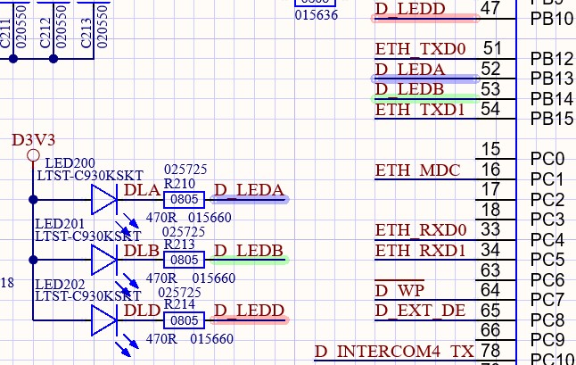
We have a problem with the PB14 pin. We use 3 pins for LED control (PB10, PB13 and PB14, see photo). The problem with the PB14 is that the LED lights up dimly without code initialization.
If PB14 is initialized as Output, Open Drain, No Pullup-Pulldown, it lights up dimly in the OFF state and normally in the ON state.
With Output Push-Pull initialization it works normally, i.e. in the OFF state the LED does not light up and in the ON state it lights up normally.
1. What could be the problem?
2. Should I use PB14 at all and is there a potential risk of later problems?
Solved! Go to Solution.
Labels:
- Labels:
-
STM32H5 Series
25 REPLIES 25
Options
- Mark as New
- Bookmark
- Subscribe
- Mute
- Subscribe to RSS Feed
- Permalink
- Email to a Friend
- Report Inappropriate Content
2024-06-13 09:20 AM
As I said, it is the same state whether code is not loaded (not programmed) or code is running.
Options
- Mark as New
- Bookmark
- Subscribe
- Mute
- Subscribe to RSS Feed
- Permalink
- Email to a Friend
- Report Inappropriate Content
2024-06-13 09:36 AM
@STOne-32 wrote:Dear @gaso111 ,
I concur what described by @AScha.3 the electronic shared should LED On when GPIO is in output 0 level to GND , either OD or Strong Push-Pull to 0 ( which seems working) . If possible to probe PB13 and PB14 and show us the signals in different combinations.
No pulses, on Pin PB14 I measured (with scope) 1,38V and on other side of resistor R213 I measured 1,50V
That means current flowing in PB14, when OD output is not active (FET is not conductive) is:
(1,50-1,38)/470=0,25mA
On PB13 I measured 1,86V and on other side of R210 the same voltage 1,86V. This means no current flows in PB13 pin.
These two GPIOs are special for USB type C _c as shared by @Tesla DeLorean and @Imen.D . We need to understand what is happening with PB14 only as it seems a path / strong leakage is created to ground even in input default state . Also sharing full schematics of power pins and boot is helpful. Let us know
Ciao,
STOne-32
P.S.
I have uploaded part of the schematic. There is VBAT (pin6) open. I connected it to VDD (3V3) and a 100nF capacitor in parallel, but no changes, LED201 lights up dimly when PB14 is not active (in OD mode).
Options
- Mark as New
- Bookmark
- Subscribe
- Mute
- Subscribe to RSS Feed
- Permalink
- Email to a Friend
- Report Inappropriate Content
2024-06-13 09:38 AM
>>I don't think, because the same effect is if uC is not flashed (board is only powered).
And I don't think that's how fuses work..
If what you've wired has established a conduction path, it really doesn't matter. A device with blank FLASH will run from ROM. PB14 is potentially set as an output, per AN2606
If the LED is emitting photons, it's because electrons are flowing, conduction is occurring, resistance is limiting the amount. Put more resistance there so it's not permitting 7mA to flow.
Tips, Buy me a coffee, or three.. PayPal Venmo
Up vote any posts that you find helpful, it shows what's working..
Up vote any posts that you find helpful, it shows what's working..
Options
- Mark as New
- Bookmark
- Subscribe
- Mute
- Subscribe to RSS Feed
- Permalink
- Email to a Friend
- Report Inappropriate Content
2024-06-13 09:56 AM - edited 2024-06-13 11:43 AM
So the bootloader is started and sets PB14 as uartTX :
ed: as SPI2 output :

When you have flashed a valid program and dont start the bootloader, (boot0 = lo ),
but your program, PB14 will work as you want.
If you feel a post has answered your question, please click "Accept as Solution".
Options
- Mark as New
- Bookmark
- Subscribe
- Mute
- Subscribe to RSS Feed
- Permalink
- Email to a Friend
- Report Inappropriate Content
2024-06-13 10:12 AM
You sure? My AN2606 for the STM32H573 shows it uses PB14 for SPI2_MISO, in a context where the STM32 is the SLAVE device. It's perhaps arguable WHEN that occurs, and if it's only after CS is seen to go low, or at reset. On the UART RX are connected to TIM inputs to measure the 0x7F 8E1 pattern before enabling the UART and UART TX output.

Tips, Buy me a coffee, or three.. PayPal Venmo
Up vote any posts that you find helpful, it shows what's working..
Up vote any posts that you find helpful, it shows what's working..
Options
- Mark as New
- Bookmark
- Subscribe
- Mute
- Subscribe to RSS Feed
- Permalink
- Email to a Friend
- Report Inappropriate Content
2024-06-13 11:39 AM
Ok ok, your right, i just mixed it up (from memory...) :)

usart1 is started on PA 9/10 .
If you feel a post has answered your question, please click "Accept as Solution".
Options
- Mark as New
- Bookmark
- Subscribe
- Mute
- Subscribe to RSS Feed
- Permalink
- Email to a Friend
- Report Inappropriate Content
2024-06-14 04:46 AM
I think the discussion is going in the wrong direction.
Once again:
1. The board is only powered, no code downloaded to the flash, nothing connected, the LED on PB14 lights up dimly. As far as I know, all GPIOs should be initialized as inputs in this state. A current of 0.25mA flows in PB14.
2. uC is programmed. All three GPIOs (PB10, PB13, PB14) are configured the same, output, open drain (OD), no pushup pushdown. The LED on PB14 lights up dimly again although the output MOSFET is not active ("1" at the output). LEDs on PB10, PB13 do not light up. If a "0" is set at the output, every LED lights up normally (as intended).
3. If PB14 is initialized as push-pull, the LED does not light up when there is a "1" at the output. When "0" is at the output, LED lights up normally (as intended)
Can someone repeat the test under the same conditions and confirm that the same thing happens?
Options
- Mark as New
- Bookmark
- Subscribe
- Mute
- Subscribe to RSS Feed
- Permalink
- Email to a Friend
- Report Inappropriate Content
2024-06-14 06:00 AM - edited 2024-06-14 07:53 AM
Ok, i tried : on H563ZIT (the "closest" to your chip, i have ) -> PB14 as open drain, hi; green LED to VDD.
Program flashed, debug at start : LED lights up dimly ...
-> run program , ok, and : LED lights up dimly ...
(on next pin, PB13 , unused, LED dark. )
So...maybe something wrong with the open drain setting here...on PB14. (I never used this pin before.)
Next : set PB14 to PP mode, hi : LED dark, as it should be.
-> also on my H563ZIT same behavior . Seems to be a chip problem. Nothing in errata.
Maybe @STOne-32 could tell something about this symptom on PB14.
So as workaround use push-pull mode, working as it should.
Otherwise there should be no problem , when using it to switch the LED in PP mode.
+
I tested PB14 as input only, LED lights up dimly ;
on hard reset pressed : LED lights up dimly.... so permanent 12Kohm pulldown on this pin.
If you feel a post has answered your question, please click "Accept as Solution".
Options
- Mark as New
- Bookmark
- Subscribe
- Mute
- Subscribe to RSS Feed
- Permalink
- Email to a Friend
- Report Inappropriate Content
2024-06-14 07:33 AM
1) When FLASH is blank it will be running the code in ROM, it doesn't just crash into an Out-of-RESET state
Tips, Buy me a coffee, or three.. PayPal Venmo
Up vote any posts that you find helpful, it shows what's working..
Up vote any posts that you find helpful, it shows what's working..
Options
- Mark as New
- Bookmark
- Subscribe
- Mute
- Subscribe to RSS Feed
- Permalink
- Email to a Friend
- Report Inappropriate Content
2024-06-14 09:05 AM
Thank you very much @AScha.3 ,
from the beginning I suspected that there was something wrong with PB14 in OD mode.
I don't know whether and how this will be included in the errata sheet.
Related Content
- Encrypt custom OBKey data provisioned with the HUK on the STM32H573 in STM32 MCUs Security
- STM32H573: ETH SWRESET fails, ETH_DMAMR_SWR stays set, timeout in STM32 MCUs Embedded software
- Code Debugging using STLINKV2 in STM32 MCUs Boards and hardware tools
- How to map HDPL levels to ST boot/ User Boot / User secure app/ user unsecure app? in STM32 MCUs Security
- Adding BSD sockets to netxDuo for LLDP in STM32 MCUs Embedded software