Turn on suggestions
Auto-suggest helps you quickly narrow down your search results by suggesting possible matches as you type.
Showing results for
- STMicroelectronics Community
- STM32 MCUs
- STM32 MCUs Products
- STM32H573 PB14
Options
- Subscribe to RSS Feed
- Mark Topic as New
- Mark Topic as Read
- Float this Topic for Current User
- Bookmark
- Subscribe
- Mute
- Printer Friendly Page
STM32H573 PB14
Options
- Mark as New
- Bookmark
- Subscribe
- Mute
- Subscribe to RSS Feed
- Permalink
- Email to a Friend
- Report Inappropriate Content
2024-06-11 10:33 AM
In our project I use STM32H573VIT6 LDO uC.
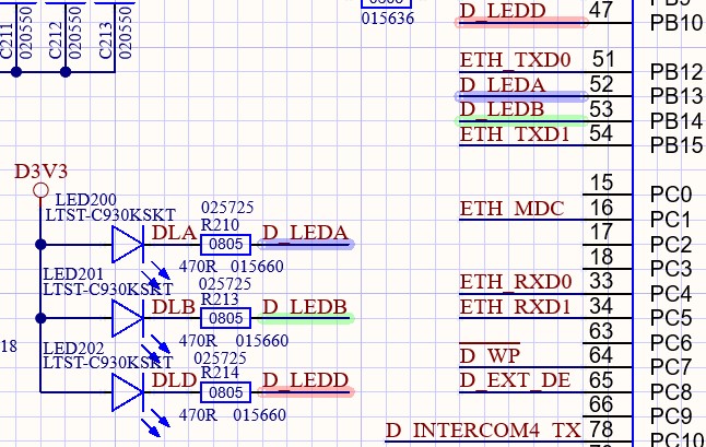
We have a problem with the PB14 pin. We use 3 pins for LED control (PB10, PB13 and PB14, see photo). The problem with the PB14 is that the LED lights up dimly without code initialization.
If PB14 is initialized as Output, Open Drain, No Pullup-Pulldown, it lights up dimly in the OFF state and normally in the ON state.
With Output Push-Pull initialization it works normally, i.e. in the OFF state the LED does not light up and in the ON state it lights up normally.
1. What could be the problem?
2. Should I use PB14 at all and is there a potential risk of later problems?
Solved! Go to Solution.
Labels:
- Labels:
-
STM32H5 series
1 ACCEPTED SOLUTION
Accepted Solutions
Options
- Mark as New
- Bookmark
- Subscribe
- Mute
- Subscribe to RSS Feed
- Permalink
- Email to a Friend
- Report Inappropriate Content
2024-06-14 6:00 AM - edited 2024-06-14 7:53 AM
Ok, i tried : on H563ZIT (the "closest" to your chip, i have ) -> PB14 as open drain, hi; green LED to VDD.
Program flashed, debug at start : LED lights up dimly ...
-> run program , ok, and : LED lights up dimly ...
(on next pin, PB13 , unused, LED dark. )
So...maybe something wrong with the open drain setting here...on PB14. (I never used this pin before.)
Next : set PB14 to PP mode, hi : LED dark, as it should be.
-> also on my H563ZIT same behavior . Seems to be a chip problem. Nothing in errata.
Maybe @STOne-32 could tell something about this symptom on PB14.
So as workaround use push-pull mode, working as it should.
Otherwise there should be no problem , when using it to switch the LED in PP mode.
+
I tested PB14 as input only, LED lights up dimly ;
on hard reset pressed : LED lights up dimly.... so permanent 12Kohm pulldown on this pin.
If you feel a post has answered your question, please click "Accept as Solution".
27 REPLIES 27
Options
- Mark as New
- Bookmark
- Subscribe
- Mute
- Subscribe to RSS Feed
- Permalink
- Email to a Friend
- Report Inappropriate Content
2024-06-12 8:17 AM - edited 2024-06-12 8:21 AM
Hello @gaso111 ,
Welcome to the Community :)
Please take in consideration the STM32H5 characteristics and limitation mentioned in this FAQ: SPI maximum clock frequency for STM32H5 MCUs devic... - STMicroelectronics Community
When your question is answered, please close this topic by clicking "Accept as Solution".
Thanks
Imen
Thanks
Imen
Options
- Mark as New
- Bookmark
- Subscribe
- Mute
- Subscribe to RSS Feed
- Permalink
- Email to a Friend
- Report Inappropriate Content
2024-06-12 9:09 AM - edited 2024-06-12 9:15 AM
I'd have to say the Data Sheet does a very poor job explaining WHY PB13/PB14 behave oddly. Inference very low sink/source current (1-2mA)
I understand the PC13,14,15 issue where they are on some low power domain.
If the pin's basically floating (OD, HIGH), how can it be leaking enough current that the LED illuminates?
Is the issue here that the LED usage has damaged the part already?
Tips, Buy me a coffee, or three.. PayPal Venmo
Up vote any posts that you find helpful, it shows what's working..
Up vote any posts that you find helpful, it shows what's working..
Options
- Mark as New
- Bookmark
- Subscribe
- Mute
- Subscribe to RSS Feed
- Permalink
- Email to a Friend
- Report Inappropriate Content
2024-06-12 10:31 AM
Hello @Imen.D ,
Thanks for quick reply
I looked at article at this link and couldn't find an answer to my question.
I use PB14 not for SPI, otherwise as GPIO, Output, Open Drain without pullup-pulldown.
I have three effects:
1. "The problem with the PB14 is that the LED lights up dimly without code initialization." (flash is not programmed)
2. "If PB14 is initialized as Output, Open Drain, No Pullup-Pulldown, it lights up dimly in the OFF state and normally in the ON state."
3. "With Output Push-Pull initialization it works normally, i.e. in the OFF state the LED does not light up and in the ON state it lights up normally."
Options
- Mark as New
- Bookmark
- Subscribe
- Mute
- Subscribe to RSS Feed
- Permalink
- Email to a Friend
- Report Inappropriate Content
2024-06-12 10:39 AM
Hello @Tesla DeLorean
You said:
"Inference very low sink/source current (1-2mA)"
Where did you get this information from?
"Is the issue here that the LED usage has damaged the part already?"
I don't think, because the same effect is if uC is not flashed (board is ohnly powered).
Options
- Mark as New
- Bookmark
- Subscribe
- Mute
- Subscribe to RSS Feed
- Permalink
- Email to a Friend
- Report Inappropriate Content
2024-06-12 11:03 AM
Table 60

Where others are 8 or 20mA out of the total GPIO current budget
Tips, Buy me a coffee, or three.. PayPal Venmo
Up vote any posts that you find helpful, it shows what's working..
Up vote any posts that you find helpful, it shows what's working..
Options
- Mark as New
- Bookmark
- Subscribe
- Mute
- Subscribe to RSS Feed
- Permalink
- Email to a Friend
- Report Inappropriate Content
2024-06-12 12:11 PM
1. Could you just check with a scope : if "dim light" , is there any pulses or just dc offset /current ?
2. I dont understand: you showed pic , LEDs connect to VDD. But then:
> OFF state the LED does not light up and in the ON state it lights up normally. <
But off=0 should light up, on=vdd should no light...??
If you feel a post has answered your question, please click "Accept as Solution".
Options
- Mark as New
- Bookmark
- Subscribe
- Mute
- Subscribe to RSS Feed
- Permalink
- Email to a Friend
- Report Inappropriate Content
2024-06-12 12:45 PM
Does the bootloader execute if the flash is not programmed? If it does, PB14 gets configured as an output.
Options
- Mark as New
- Bookmark
- Subscribe
- Mute
- Subscribe to RSS Feed
- Permalink
- Email to a Friend
- Report Inappropriate Content
2024-06-12 2:47 PM
Dear @gaso111 ,
I concur what described by @AScha.3 the electronic shared should LED On when GPIO is in output 0 level to GND , either OD or Strong Push-Pull to 0 ( which seems working) . If possible to probe PB13 and PB14 and show us the signals in different combinations. These two GPIOs are special for USB type C _c as shared by @Tesla DeLorean and @Imen.D . We need to understand what is happening with PB14 only as it seems a path / strong leakage is created to ground even in input default state . Also sharing full schematics of power pins and boot is helpful. Let us know
Ciao,
STOne-32
Options
- Mark as New
- Bookmark
- Subscribe
- Mute
- Subscribe to RSS Feed
- Permalink
- Email to a Friend
- Report Inappropriate Content
2024-06-13 9:17 AM
@AScha.3 wrote:1. Could you just check with a scope : if "dim light" , is there any pulses or just dc offset /current ?
No pulses, on Pin PB14 I measured (with scope) 1,38V and on other side of resistor R213 I measured 1,50V,
That means current flowing in PB14, when OD output is not active (FET is not conductive) is:
(1,50-1,38)/470=0,25mA
2. I dont understand: you showed pic , LEDs connect to VDD. But then:
> OFF state the LED does not light up and in the ON state it lights up normally. <
But off=0 should light up, on=vdd should no light...??
This applies to push-pull output, but not to open drain (OD)
Related Content
- CSConnect Errors When Generating Custom Project in STM32 MCUs Motor control
- STM32H5 Cannot enter system bootloader from software in STM32 MCUs Embedded software
- stm32h573 otp memory in STM32 MCUs Security
- SDMMC2 build fails - Unknown destination type (ARM/Thumb) in STM32CubeIDE (MCUs)
- STM32H5 Host mode with an external 4-port USB Hub in STM32 MCUs Embedded software