Turn on suggestions
Auto-suggest helps you quickly narrow down your search results by suggesting possible matches as you type.
Showing results for
- STMicroelectronics Community
- STM32 MCUs
- STM32 MCUs Products
- My problem: stm32h743 ADC does not convert small s...
Options
- Subscribe to RSS Feed
- Mark Topic as New
- Mark Topic as Read
- Float this Topic for Current User
- Bookmark
- Subscribe
- Mute
- Printer Friendly Page
My problem: stm32h743 ADC does not convert small signals(about 1-5mv) correctly
Options
- Mark as New
- Bookmark
- Subscribe
- Mute
- Subscribe to RSS Feed
- Permalink
- Email to a Friend
- Report Inappropriate Content
2020-01-09 12:01 AM
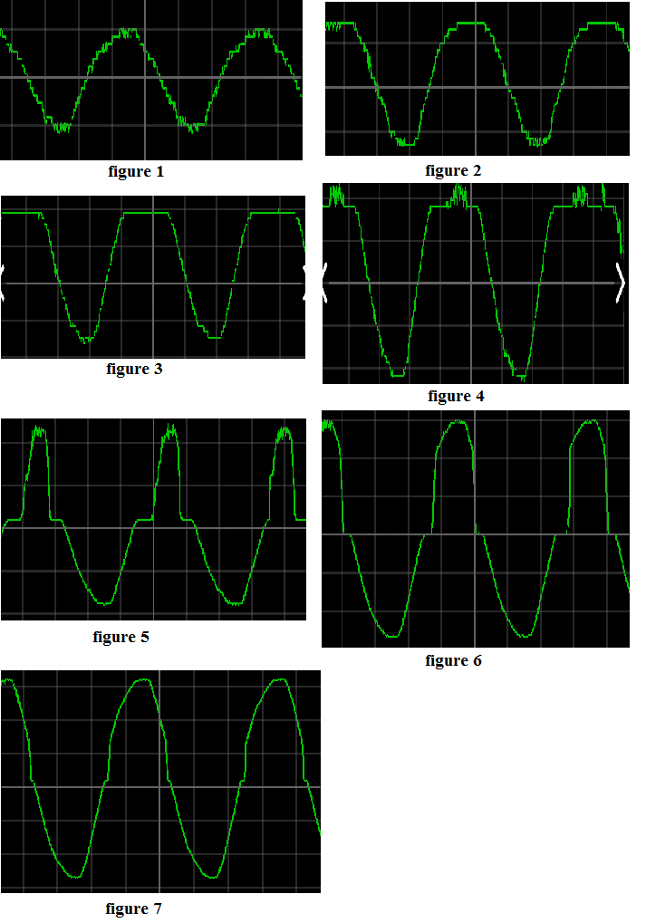
I configure ADC1 and ADC2 in Dual mode, 16 bit resolution, differential-ended. I use CubeMx to initialize ADC. I want measure voltage and current. My project samples the signals and then sends them to the computer for plotting and logging by the WiFi module. When the amplitude of voltage and current are too small, the ADC does not convert the signals correctly. I have attached figures of a logged signal. In these figures the amplitude of voltage changes from 1mV to 9 mV. Figures show that, a part of the signal has not been converted correctly.

This behaviour is seen in other channel that you can see in below figure.

In my hardware, the signal first passes through a differential-ended amplifier (AD8132) and then enters the ADC. The common mode voltage at the amplifier outputs is Vref/2(There is some potential difference (about a few millivolts) between the amplifier outputs). Schematic of the amplifier is attached.

ADCs are initialized by below functions. Sampling frequency is 12KHz.
static void MX_ADC1_Init(void)
{
ADC_MultiModeTypeDef multimode = {0};
ADC_ChannelConfTypeDef sConfig = {0};
hadc1.Instance = ADC1;
hadc1.Init.ClockPrescaler = ADC_CLOCK_ASYNC_DIV6;
hadc1.Init.Resolution = ADC_RESOLUTION_16B;
hadc1.Init.ScanConvMode = ADC_SCAN_ENABLE;
hadc1.Init.EOCSelection = ADC_EOC_SEQ_CONV;
hadc1.Init.LowPowerAutoWait = DISABLE;
hadc1.Init.ContinuousConvMode = DISABLE;
hadc1.Init.NbrOfConversion = 3;
hadc1.Init.DiscontinuousConvMode = DISABLE;
hadc1.Init.ExternalTrigConv = ADC_EXTERNALTRIG_T6_TRGO;
hadc1.Init.ExternalTrigConvEdge = ADC_EXTERNALTRIGCONVEDGE_FALLING;
hadc1.Init.ConversionDataManagement = ADC_CONVERSIONDATA_DMA_CIRCULAR;
hadc1.Init.Overrun = ADC_OVR_DATA_PRESERVED;
hadc1.Init.LeftBitShift = ADC_LEFTBITSHIFT_NONE;
hadc1.Init.OversamplingMode = ENABLE;
hadc1.Init.Oversampling.Ratio = 31;
hadc1.Init.Oversampling.RightBitShift = ADC_RIGHTBITSHIFT_5;
hadc1.Init.Oversampling.TriggeredMode = ADC_TRIGGEREDMODE_SINGLE_TRIGGER;
hadc1.Init.Oversampling.OversamplingStopReset = ADC_REGOVERSAMPLING_CONTINUED_MODE;
if (HAL_ADC_Init(&hadc1) != HAL_OK)
{
Error_Handler();
}
multimode.Mode = ADC_DUALMODE_REGSIMULT_INJECSIMULT;
multimode.DualModeData = ADC_DUALMODEDATAFORMAT_32_10_BITS;
multimode.TwoSamplingDelay = ADC_TWOSAMPLINGDELAY_1CYCLE;
if (HAL_ADCEx_MultiModeConfigChannel(&hadc1, &multimode) != HAL_OK)
{
Error_Handler();
}
sConfig.Channel = ADC_CHANNEL_2;
sConfig.Rank = ADC_REGULAR_RANK_1;
sConfig.SamplingTime = ADC_SAMPLETIME_8CYCLES_5;
sConfig.SingleDiff = ADC_DIFFERENTIAL_ENDED;
sConfig.OffsetNumber = ADC_OFFSET_NONE;
sConfig.Offset = 0;
if (HAL_ADC_ConfigChannel(&hadc1, &sConfig) != HAL_OK)
{
Error_Handler();
}
sConfig.Channel = ADC_CHANNEL_3;
sConfig.Rank = ADC_REGULAR_RANK_2;
if (HAL_ADC_ConfigChannel(&hadc1, &sConfig) != HAL_OK)
{
Error_Handler();
}
sConfig.Channel = ADC_CHANNEL_4;
sConfig.Rank = ADC_REGULAR_RANK_3;
if (HAL_ADC_ConfigChannel(&hadc1, &sConfig) != HAL_OK)
{
Error_Handler();
}
HAL_ADCEx_Calibration_Start(&hadc1, LL_ADC_CALIB_LINEARITY, ADC_DIFFERENTIAL_ENDED);
}
static void MX_ADC2_Init(void)
{
ADC_ChannelConfTypeDef sConfig = {0};
hadc2.Instance = ADC2;
hadc2.Init.ClockPrescaler = ADC_CLOCK_ASYNC_DIV6;
hadc2.Init.Resolution = ADC_RESOLUTION_16B;
hadc2.Init.ScanConvMode = ADC_SCAN_ENABLE;
hadc2.Init.EOCSelection = ADC_EOC_SEQ_CONV;
hadc2.Init.LowPowerAutoWait = DISABLE;
hadc2.Init.ContinuousConvMode = DISABLE;
hadc2.Init.NbrOfConversion = 3;
hadc2.Init.DiscontinuousConvMode = DISABLE;
hadc2.Init.ConversionDataManagement = ADC_CONVERSIONDATA_DMA_CIRCULAR;
hadc2.Init.Overrun = ADC_OVR_DATA_PRESERVED;
hadc2.Init.LeftBitShift = ADC_LEFTBITSHIFT_NONE;
hadc2.Init.OversamplingMode = ENABLE;
hadc2.Init.Oversampling.Ratio = 31;
hadc2.Init.Oversampling.RightBitShift = ADC_RIGHTBITSHIFT_5;
hadc2.Init.Oversampling.TriggeredMode = ADC_TRIGGEREDMODE_SINGLE_TRIGGER;
hadc2.Init.Oversampling.OversamplingStopReset = ADC_REGOVERSAMPLING_CONTINUED_MODE;
if (HAL_ADC_Init(&hadc2) != HAL_OK)
{
Error_Handler();
}
sConfig.Channel = ADC_CHANNEL_18;
sConfig.Rank = ADC_REGULAR_RANK_1;
sConfig.SamplingTime = ADC_SAMPLETIME_8CYCLES_5;
sConfig.SingleDiff = ADC_DIFFERENTIAL_ENDED;
sConfig.OffsetNumber = ADC_OFFSET_NONE;
sConfig.Offset = 0;
if (HAL_ADC_ConfigChannel(&hadc2, &sConfig) != HAL_OK)
{
Error_Handler();
}
sConfig.Channel = ADC_CHANNEL_5;
sConfig.Rank = ADC_REGULAR_RANK_2;
if (HAL_ADC_ConfigChannel(&hadc2, &sConfig) != HAL_OK)
{
Error_Handler();
}
sConfig.Channel = ADC_CHANNEL_2;
sConfig.Rank = ADC_REGULAR_RANK_3;
if (HAL_ADC_ConfigChannel(&hadc2, &sConfig) != HAL_OK)
{
Error_Handler();
}
HAL_ADCEx_Calibration_Start(&hadc2, LL_ADC_CALIB_LINEARITY, ADC_DIFFERENTIAL_ENDED);
}
Labels:
- Labels:
-
ADC
-
STM32H7 series
23 REPLIES 23
Options
- Mark as New
- Bookmark
- Subscribe
- Mute
- Subscribe to RSS Feed
- Permalink
- Email to a Friend
- Report Inappropriate Content
2020-09-14 11:04 PM
I can't solve my problem
Options
- Mark as New
- Bookmark
- Subscribe
- Mute
- Subscribe to RSS Feed
- Permalink
- Email to a Friend
- Report Inappropriate Content
2020-09-15 07:45 AM
If you are running at maximum ADC clock speed, try 1/2 maximum.
The other workaround is shift your low level signal away from the mid ADC range (MSB transition region will have the greatest LSB step error)
Another common mistake is to rely on single supply RRIO opamps for buffering < 100 mV signal
Options
- Mark as New
- Bookmark
- Subscribe
- Mute
- Subscribe to RSS Feed
- Permalink
- Email to a Friend
- Report Inappropriate Content
2020-09-16 12:53 AM
The ADC is used to measure ac current, so, I shift the current signal to 1.65V when the real current is 0. It's just the mid ADC range. So I think what you said is right . But I don't know the background why MSB transition region will have the greatest LSB step error in such case. Could you please explain more about this
Options
- Mark as New
- Bookmark
- Subscribe
- Mute
- Subscribe to RSS Feed
- Permalink
- Email to a Friend
- Report Inappropriate Content
2020-09-16 05:11 AM
The MSB resistor must be accurate to at least 1 LSB. (1/2048 in 12 bit DAC )
The LSB resistor on the other hand can be off by 10% without contributing noticeable error.
- « Previous
- Next »
Related Content
- [STM32H753] USB33RDY is not asserting in STM32 MCUs Embedded software
- LibUSB Error suddenly appearing in STM32CubeIDE (MCUs)
- Can set option bytes in STM32 ST-LINK Utility but not STM32CubeProgrammer, Why? in STM32 MCUs Boards and hardware tools
- IR Output Polarity in STM32 MCUs Boards and hardware tools
- STM32G431 Encoder Mode Issue in STM32 MCUs Products