Turn on suggestions
Auto-suggest helps you quickly narrow down your search results by suggesting possible matches as you type.
Showing results for
- STMicroelectronics Community
- STM32 MCUs
- STM32 MCUs Products
- Re: How do you set STM32G031 advanced timer TIM1 c...
Options
- Subscribe to RSS Feed
- Mark Topic as New
- Mark Topic as Read
- Float this Topic for Current User
- Bookmark
- Subscribe
- Mute
- Printer Friendly Page
How do you set STM32G031 advanced timer TIM1 clock source at the 128 MHz maximum frequency ?
Options
- Mark as New
- Bookmark
- Subscribe
- Mute
- Subscribe to RSS Feed
- Permalink
- Email to a Friend
- Report Inappropriate Content
2022-05-13 09:58 AM
Hello,
I'm currently working on an STM32G031G8U on a custom PCB. I can't really debug the code as I don't have access to ST-Link or SWDIO/SWCLK pins.
I haven't managed to set TIM1 internal clock to 128 MHz as stated in the reference manual (section 5.2.13) and the datasheet (section 3.16).
I'm currently using the TIM1 at 64 MHz to fire an interrupt every 64 µs. I reduced the ISR code to toggle a GPIO output pin (led), wait a few µs, and toggle the pin again. Then I observe pin output on an oscilloscope and I do measure the expected 64µs period. So far, so good.
When I try to set TIM1 at 128 MHz, the processor seems to go into fault mode (LED is not being driven anymore) instead of having a period twice as fast as the former one.
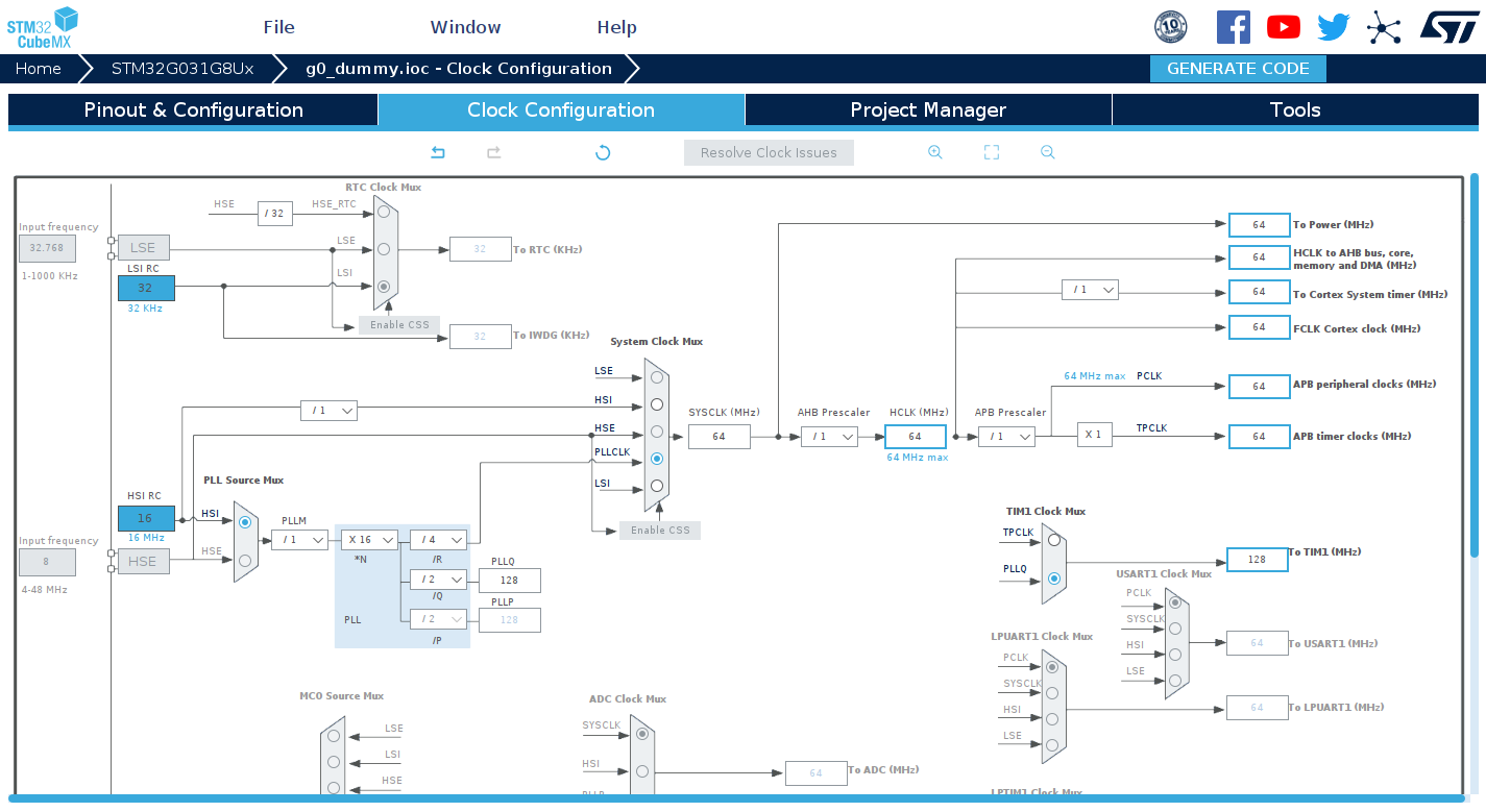
I used two configs on CubeMX to generate the RCC and TIM config code to set the timer at 128 MHz (refer to the attached pictures).
The first one uses TPCLK as input, but I think there's an issue with CubeMX for this config, as it uses a x2 multiplier although prescaler is set to 1. The reference manual actually contradicts that config stating that a prescaler value of 1 implie a multiplier value for TPCLK of 1.
The second config uses the PLLQ as input to run at 128 MHz ( M = 1, N = 16, R = 4, Q = 2, P = 2 with this latter one being grayed out). When I compile and run the code, the processor goes into fault mode although I'm using generated code.
I attached the source file. I tried to leave only the relevant code. I'm flashing the STM32 with a custom bootloader as well as a slightly custom linker script (to put some critical code on RAM), so you might not be able to compile and flash it on your side without some modifications.
The commented RCC config is the one at 64 MHz, working fine. The RCC config being compiled is the one that makes the processor go into fault, using PLLQ.
I did not put the config using TPCLK because I don't think it's a valid one.
If anyone has any clues as to why this fail, the help would be much appreciated.
Thank you in advance
Solved! Go to Solution.
Labels:
- Labels:
-
STM32G0 Series
-
TIM
1 ACCEPTED SOLUTION
Accepted Solutions
Options
- Mark as New
- Bookmark
- Subscribe
- Mute
- Subscribe to RSS Feed
- Permalink
- Email to a Friend
- Report Inappropriate Content
2022-05-16 07:41 AM
I was able to configure the desired TIM1 at 128 MHz as needed.
The process would go into fault because in the code I posted, I was trying modify PLL coefficient values without making sure that the system clock wasn't using the PLLCLK as input.
Switching to HSI clock as system clock before modifying the PLL values and then switching back to PLL clock did the trick. I can now measure the expected period on the GPIO driven led.
	/* Switch on HSI Clock before setting PLL clock*/
	RCC_ClkInitStruct.ClockType = RCC_CLOCKTYPE_HCLK | RCC_CLOCKTYPE_SYSCLK ;
	RCC_ClkInitStruct.SYSCLKSource = RCC_SYSCLKSOURCE_HSI;
	RCC_ClkInitStruct.AHBCLKDivider = RCC_SYSCLK_DIV1;
	RCC_ClkInitStruct.APB1CLKDivider = RCC_HCLK_DIV1;
	if (HAL_RCC_ClockConfig(&RCC_ClkInitStruct, FLASH_LATENCY_2) != HAL_OK)
		return -1;
Moreover PLLP divider needs to be set to 4, as it is required that PLLP does not exceed 122 MHz.
Thank you @Community member for the hints, looking in depth into generated code and to example code on F0 reference manual got me back on track.
3 REPLIES 3
Options
- Mark as New
- Bookmark
- Subscribe
- Mute
- Subscribe to RSS Feed
- Permalink
- Email to a Friend
- Report Inappropriate Content
2022-05-14 12:21 AM
You should try to debug this on a "known good" Nucleo/Disco board, to 1. exclude problems with power supply (there's more current consumption at higher frequencies); 2. to be able to debug directly.
> The reference manual actually contradicts that config stating that a prescaler value of 1 implie a multiplier value for TPCLK of 1.
Take it as a lesson to not rely on CubeMX.
> The second config uses the PLLQ as input to run at 128 MHz ( M = 1, N = 16, R = 4, Q = 2, P =
> with this latter one being grayed out). When I compile and run the code, the processor goes into
> fault mode although I'm using generated code.
The same thing applies: generated code does not mean it's good.
Write your own, making sure FLASH latency and VOS settings are appropriate for the frequencies used. If a minimal code, which does not rely on Cube, setting up clocks and TIM1, still won't work, post it.
JW
Options
- Mark as New
- Bookmark
- Subscribe
- Mute
- Subscribe to RSS Feed
- Permalink
- Email to a Friend
- Report Inappropriate Content
2022-05-16 01:23 AM
Thank you for the hints.
I don't think power supply is an issue here as the PCB is supplied with a DC supply and is currently used to drive loads such as motors without issues.
I wish I could get my hand on a Nucleo/Disco board with a G0 but unfortunately all suppliers are out of stock in my region.
I'll do just what you suggested, I'll keep you guys in touch of any progress.
Options
- Mark as New
- Bookmark
- Subscribe
- Mute
- Subscribe to RSS Feed
- Permalink
- Email to a Friend
- Report Inappropriate Content
2022-05-16 07:41 AM
I was able to configure the desired TIM1 at 128 MHz as needed.
The process would go into fault because in the code I posted, I was trying modify PLL coefficient values without making sure that the system clock wasn't using the PLLCLK as input.
Switching to HSI clock as system clock before modifying the PLL values and then switching back to PLL clock did the trick. I can now measure the expected period on the GPIO driven led.
	/* Switch on HSI Clock before setting PLL clock*/
	RCC_ClkInitStruct.ClockType = RCC_CLOCKTYPE_HCLK | RCC_CLOCKTYPE_SYSCLK ;
	RCC_ClkInitStruct.SYSCLKSource = RCC_SYSCLKSOURCE_HSI;
	RCC_ClkInitStruct.AHBCLKDivider = RCC_SYSCLK_DIV1;
	RCC_ClkInitStruct.APB1CLKDivider = RCC_HCLK_DIV1;
	if (HAL_RCC_ClockConfig(&RCC_ClkInitStruct, FLASH_LATENCY_2) != HAL_OK)
		return -1;
Moreover PLLP divider needs to be set to 4, as it is required that PLLP does not exceed 122 MHz.
Thank you @Community member for the hints, looking in depth into generated code and to example code on F0 reference manual got me back on track.
Related Content
- Correct ADC settings for DMA in STM32 MCUs Products
- Problem with SPI Communication - Nucleo U575ZI-Q/STEVAL-MKI168V1 in STM32 MCUs Boards and hardware tools
- STM32H7 TIM1 PWM Issue in STM32 MCUs Products
- TIM2/TIM5 works but same code does not work for any other timers in STM32 MCUs Products
- Generating four synchronised Signals with Timer, PWM, and DMA (XY2-100) in STM32 MCUs Embedded software