Turn on suggestions
Auto-suggest helps you quickly narrow down your search results by suggesting possible matches as you type.
Showing results for
- STMicroelectronics Community
- STM32 MCUs
- STM32 MCUs products
- Step Signals at The Conversion Output of The ADC
Options
- Subscribe to RSS Feed
- Mark Topic as New
- Mark Topic as Read
- Float this Topic for Current User
- Bookmark
- Subscribe
- Mute
- Printer Friendly Page
Step Signals at The Conversion Output of The ADC
Options
- Mark as New
- Bookmark
- Subscribe
- Mute
- Subscribe to RSS Feed
- Permalink
- Email to a Friend
- Report Inappropriate Content
2020-02-24 01:04 PM
Hello,
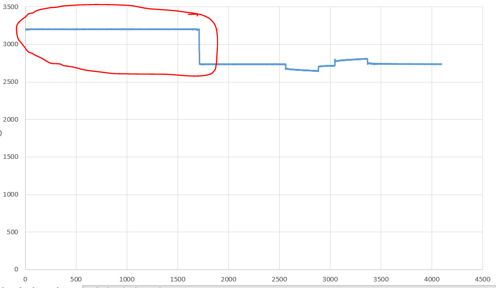
I use internal ADC of the STM32F767 microprocessor. When I plot the converted data in the Excel, I see a step signals initially. But when I check the analog signal input of the ADC with oscilloscope, there is no signal as step signals initially. Does anyone have an idea about why there is a signal like this?
In the picture, I circled with a red of the problem.
Thank you,
Labels:
- Labels:
-
ADC
-
STM32F7 Series
5 REPLIES 5
Options
- Mark as New
- Bookmark
- Subscribe
- Mute
- Subscribe to RSS Feed
- Permalink
- Email to a Friend
- Report Inappropriate Content
2020-02-24 01:07 PM
There are many things to consider when converting analog signal. You do not tell of any measure you have taken, so anything is guessing. Learn about input impedance, sampling time and much more....
Options
- Mark as New
- Bookmark
- Subscribe
- Mute
- Subscribe to RSS Feed
- Permalink
- Email to a Friend
- Report Inappropriate Content
2020-02-24 01:10 PM
After the end of the step signal, the converted signal is true. I can share what information you need.
Options
- Mark as New
- Bookmark
- Subscribe
- Mute
- Subscribe to RSS Feed
- Permalink
- Email to a Friend
- Report Inappropriate Content
2020-02-24 01:38 PM
Also when I enable the DMA continuous request, there is no step signal initially. But in this case I couldn't catch the signal properly. When I disable the DMA continous request mode, I catch the signal but there is a step signal initially like in the first post.
Options
- Mark as New
- Bookmark
- Subscribe
- Mute
- Subscribe to RSS Feed
- Permalink
- Email to a Friend
- Report Inappropriate Content
2020-02-24 09:34 PM
What do you exactly mean by "initially"?
VDDA/VREF unstable?
JW
Options
- Mark as New
- Bookmark
- Subscribe
- Mute
- Subscribe to RSS Feed
- Permalink
- Email to a Friend
- Report Inappropriate Content
2020-02-24 10:07 PM
> But when I check the analog signal input of the ADC with oscilloscope, there is no signal as step signals initially.
How did the corresonding input signal(s) look like ?
First, apply a known DC voltage to the ADC input and check the ADC results.
Then, apply a reference signal of a frequency relevant for you application, and check the ADC results.
Related Content
- Optical SPDIF - MCU takes as input - Process - Output the SPDIF signal in STM32 MCUs products
- STM32H750 internal temperature sensor wrong reading in STM32 MCUs products
- LPTIM wb55 issues with HAL_LPTIM_AutoReloadMatchCallback in STM32 MCUs products
- Interrupts occur twice when using ADC injected channel conversion mode. in STM32 MCUs Motor control
- ADC not working at all - only output is "0" in STM32 MCUs Embedded software