Get ready for the STM32 Summit 2026 | Online, November 3
Join discussions in the Product Forums. Ask questions, learn from your peers, and share insights on ST solutions to accelerate your design journey.
Most recent activity
I am using STM32MP235 on custom board. At some point, I wanted to update the firmware via SFU using STM32CubeProgrammer.I rebooted the board in USB mode (setting the boot mode to BOOT using the pins) and launched CubeProgrammer.TF-A-programmer-usb loaded onto the board normally, but after that, the board stopped responding via DFU.After a power reset, the board boots in DFU mode, even though the internal eMMC contains the old firmware, and the default boot mode is eMMC.As soon as TF-A is loaded onto the board, the board disappears. Nothing is written to the debug port, making it seem as if TF-A failed to boot.I tried using ROMTrace TF-A. The behavior is exactly the same, and no trace is output to the port.Pin PG4 (FAILBOOTN) is connected to a red LED. During normal boot, this LED starts blinking, and after flashing the TF-A (whether via USB or Serial), it turns solid.The documentation says that the FAILBOOTN LED blinks when the board initially boots in USB/UART mode, meaning it doesn't
For STM32U575/U585, the STM32U5 Customer Webinar says that the 256-bit BHK is “Generated by the secure boot code”. Is the intended implementation to generate 256 bits from the STM32 RNG when the BHK backup registers are uninitialized, or should secure boot restore/derive BHK from a persistent OEM-provisioned secret? Is there ST reference source code implementing the generation, TAMP_BKP[7:0]R write, and BHKLOCK sequence?
Good morning, I’m trying to build a project based on EVLSPIN32G0B2 evaluation board.I’m trying to establish a connection between the board and the STM32CubeProgrammer.Checking the electrical scheme, I saw that the USB connector on the evaluation board is connected to the port PB6 and PB7 (pins 45 and 46 of the SPIN32G0B2) which are the wires of an I2C port. Do I need any interface ?What’s the secret for a working connections ? ThanksStefano P.S. there’s another post on the same argument I wrote few days ago.I can’t delete it, can a moderator delete it for me ? It is useless. Thanks.
I am troubleshooting a USB device that is not being detected by my computer. What are the main hardware and software checks I should perform to determine whether the problem is related to the USB connection, drivers, or the device itself?
I am trying to jump from bootloader to application at address 0x08004800 i STM32G070 but it crashes.The same code worked fine jumping to address 0x08007000Bootloader jump looks like this:#define BL_FLASH_START 0x08000000#define BL_FLASH_SIZE 0x4800 // 18 kB reserverade för BL, OBS! Startadress måste vara alignad mot 32 byte, dvs jämnt delbar med 32..#define BL_FLASH_END (BL_FLASH_START + BL_FLASH_SIZE-4) // 4 byte checksumma#define APP_FLASH_BANK_SIZE 0xDC00 // 55 kB / appl bank// Defines för applikationen#define FLASH_START (BL_FLASH_START + BL_FLASH_SIZE)....HW_WD_Trig();JumpAddress = *(uint32_t*) (FLASH_START + 4);Jump_To_Application = (pFunction) JumpAddress;// disable global interrupt__disable_irq();JumpAddress = *(uint32_t*) (FLASH_START + 4);Jump_To_Application = (pFunction) JumpAddress;/* Initialize user application's Stack Pointer */__set_MSP(*(uint32_t*) (FLASH_START));Jump_To_Application(); .ld for bor bootloader looks like:/* Entry Point */ENTRY(Reset_Handler)/* Highest ad
Hello, I am trying to communicate with a VL53L1X sensor using a PIC18F16Q41 hardware I2C peripheral (MCC-generated driver). The sensor module is AE-VL53L1X from Akizuki Denshi (Japan), which includes the original ST VL53L1X sensor and onboard level shifter. Current issue: The sensor ACKs correctly, but reading the Model ID register (0x010F) always returns 0x00 instead of the expected 0xEA. Current I2C sequence: START W 0x29 ACK 0x01 ACK 0x0F ACK STOP (wait about 1 ms) START R 0x29 ACK 0x00 NACK (expected 0xEA) STOP What I already confirmed: * Wrong I2C addresses correctly return NACK from the sensor * XSHUT is correctly pulled up * Sensor power is stable before PIC startup * Oscilloscope confirms correct ACK/NACK behavior Important comparison: Using a RATOC USB-I2C converter with the same sensor module, register 0x010F correctly returns 0xEA. So the sensor module itself appears to work correctly. I compared the oscilloscope waveforms between RATOC and PIC. One difference i
Hi all:I have a number of firmwares which use the older Standard Peripheral Library for STM32F4xx etc.I could switch to the new Low-Layer drivers, but I doubt it is worth the effort.I actually found the old Standard Peripheral Libraries quite all right. Unfortunately, STM is not maintaining them anymore, even in the face of obvious bugs like this one:Standard Peripheral Library limits STM32F4xx USART to 7.5 Mbit/s, instead of max 10.5 Mbit/shttps://community.st.com/stm32-mcus-products-25/standard-peripheral-library-limits-stm32f4xx-usart-to-7-5-mbit-s-instead-of-max-10-5-mbit-s-82037Are there any community forks of the Standard Peripheral Libraries I could switch to?Thanks in advance, rdiez
HelloST Edge AI: Guide for STM32MPU 、 Section 3.2.1. Referring to “Generate NBG from TensorFlow™ Lite or ONNX,”I converted the .tflite file downloaded from ModelZoo to .nb, but I’m getting an error.$ /opt/ST/STEdgeAI/4.0/Utilities/linux/stedgeai generate -m ./yolov8n_256_quant_pc_uf_od_coco-person-st.tflite --target stm32mp25ST Edge AI Core v4.0.1-20581 7ed50de05E102(CliArgumentError): stm32mp25 not recognized as target. Supported targets areispu --device DEVICEmlcstm32f4stm32l4stm32l4pstm32g4stm32f3stm32wbstm32n6 [--st-neural-art]stm32f0stm32l0stm32g0stm32c0stm32wlstm32v8stm32u3 [--hsp]stm32h7stm32f7stm32u5stm32l5stm32h5stm32c5stm32mp157cIf you change the target name slightly, you'll get the following error: $ /opt/ST/STEdgeAI/4.0/Utilities/linux/stedgeai generate -m ./yolov8n_256_quant_pc_uf_od_coco-person-st.tflite --target stm32mp2ST Edge AI Core v4.0.1-20581 7ed50de05E102(CliArgumentError): stm32mp2 is not availableCould you tell me how to convert a .tflite file to
Dear ST Community,We are working on a custom board using the STM32H747XG controller with a MIPI DSI display interface.Our display panel is RK055MHD091A0-CTG, with a resolution of 720 × 1280. The display uses the HX8394-F TFT driver IC, and we are using the 2-lane MIPI DSI interface: DSI Data Lane 0 DSI Data Lane 1 DSI Clock Lane We have configured the STM32H747 DSI Host in Video Mode and are using LTDC with an SDRAM framebuffer.The HX8394-F supports DBI Type C option 1, 3-wire serial bus to access command set under DSI I/F. The 3-wire serial bus is use: chip select line (CSX), serial input data (SDI),serial output data (SDO) and serial transfer clock line (SCL).According to the HX8394-F display driver requirements, the panel requires an initialization sequence with several commands for configuring parameters such as power, MIPI settings, gamma, GIP, etc., before starting the display.We would like guidance on the correct way to send these HX8394-F initialization commands from the ST
I am trying to send GPS data from one B-L072Z-LRWAN1 to another B-L072Z-LRWAN1. There are 3 tasks to do this.1. Get GPS data using a B-L072Z-LRWAN1.2. Send text data from one B-L072Z-LRWAN1 to another B-L072Z-LRWAN1 using PingPong project.3. Combine 1 and 2, send GPS data from one B-L072Z-LRWAN1 to another B-L072Z-LRWAN1.Tasks 1 and 2 were successful, but I cannot do No.3 task. I compared the code that retrieves GPS data with the code that does nothing, and wrote the differences to the PingPong project. I've attached a portion of the code below. Could you give me a suggestion? if (transferComplete) { snprintf(sval , sizeof(sval), "%s\r\n","test"); HAL_UART_Transmit( &huart2, sval, strlen(sval) + 1, 0xFFFF); MX_SubGHz_Phy_Process(); transferComplete = 0; /* Restart DMA reception */ HAL_NVIC_SystemReset(); HAL_UARTEx_ReceiveToIdle_DMA(&huart1, gpsBuffer, GPS_BUFFER_SIZE); __HAL_DMA_DISABLE_IT(&hdma_usart1_rx, DMA_IT_HT); } HAL_Delay(1000);
This account only shares restored community content posted by members between May 22 and June 9, 2026, who did not register for the new community.using the STM32G473CET6 and have configured 4 ADC channels. When scan mode is enabled, the readings from the first two channels are normal, but for the last two channels with an active voltage signal input, the ADC still shows readings of over a thousand when 0V is input. When I disconnect the external interface, I find that this channel has a voltage over 1.3V after initialization. Why is this happening? Later, I tried enabling single-read mode and initializing the ADC interface each time before reading, and the values read were normal.
Above image you can see in toolchain option STM32IDE is disable . also i am facimng issure i =n import examples which stm32 provided for reference . you can also refer my shared video.
Does the ST LINK v2 support STM32MP235F connection?
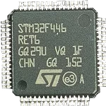
Dear STMicroelectronics Technical Support,I am working on a custom PCB using the STM32F446RET6 in LQFP64 package, and I am facing a hardware issue where the MCU is not detected by ST-LINK and the VCAP1 voltage is much lower than expected.I would appreciate your help in identifying the root cause.MCU and power configurationMCU: STM32F446RET6 – LQFP64 VDD = 3.3V VDDA = 3.3V VBAT = 3.3V VCAP1 = Pin 30 VSS = Pin 31 → GND VCAP1 capacitor = 4.7µF ceramic MLCC, 6.3V, 0603 VCAP1 capacitor is connected between VCAP1 and GND NRST = 3.3V BOOT0 has a pull-down resistor SWD interface is connected to an ST-LINK debuggerCurrent symptomsThe 3.3V supply is stable on the MCU.However:VCAP1 is only around 0.4–0.6V It does not remain around the expected internal core voltage The MCU is not detected by ST-LINK The same behavior occurs after replacing the MCUTroubleshooting already performedI have already performed the following tests:Checked the 3.3V supply and confirmed that VDD and VDDA are stable at 3.3V
I recently purchased a new Windows on ARM laptop—a Snapdragon X2 Elite, to be exact. Like many others, I ran into issues getting the ST-LINK/V2 to work because of driver compatibility. I ended up working on a fix that allows STM32CubeProgrammer to connect to the ST-LINK/V2 using the Windows WinUSB driver. Simply changing the driver to WinUSB isn’t enough—the ST-LINK device interface GUID also needs to be added/updated so that STM32CubeProgrammer can properly detect and communicate with the probe. Updating the ST-LINK/V2 firmware presented another problem. When the ST-LINK enters firmware-update mode, it enumerates as a different USB device. This means the firmware-update/DFU interface also needs to be configured to use WinUSB.With this fix, you can now update the ST-LINK/V2 firmware directly from a Windows on ARM computer. There is no longer a need to connect the ST-LINK/V2 to an Intel/AMD Windows computer just to perform a firmware update. The next issue was STM32CubeIDE. Even though
Subject edited to mention ARM64 - p.a. Hi everyone, I am having trouble getting my STM32 NUCLEO - F411RE setup. When I attempt to run a simple program through CubeIDE I am met with "NO ST-LINK detected! Please connect ST-LINK and restart the debug session." It also returns the same error when I attempt to run other programs.Here's what I have tried thus far : - In my Device Manager I can see "ST-Link Debug" which has the status: "The drivers for this device are not installed. (Code 28) There are no compatible drivers for this device. To find a driver for this device, click Update Driver." I've tried both the "search automatically for drivers" and "Browse my computer for drivers" (using C:\Users\jthom\OneDrive\Desktop\stsw-link009\amd64), however both have thus far failed. - Restarted computer multiple times - I've installed CubeProgrammer however when I attempt to connect ST-LINK through there I am met with: "Err
Hi all:On the following page:https://www.st.com/en/embedded-software/stm32cubeg0.htmlThere is an option to download Patch_CubeG0 v1.6.3, but the file named stm32cubeg0-v1-6-3.zip only weighs 70 MB, and, depending on the unzip compressor, I get errors like "Unexpected end of archive" or "End-of-central-directory signature not found".I have tried downloading the file with different browsers and tools, to no avail.I can download the previous version stm32cubeg0-v1-6-2.zip without no problems. It is much bigger and identical to the one I had downloaded a long time ago.Is the v1.6.3 patch file corrupted on the st.com server?If I try to download the full version, I only get v1.6.0. If I click on the "Get from GitHub" button next to it, I get a full v1.6.3 called STM32CubeG0-1.6.3.zip, but then directory "Drivers/STM32G0xx_HAL_Driver/" is empty.I could manually piece the latest versions together from Git, but this is time consuming and error prone.Is there another way?Thanks in advance, rdie
Have use of L6599D in many power supplies from 50W to 300W, is L6599AD a direct functional replacement for any applications is expected to work exactly the same? Thank you.
大家好!问题是这样的: 我正在尝试使用 STM32 ISP-IQTune 应用程序通过 STM32N657X0H3Q 板读取 PC 上的 IMX335 相机数据。但是,IQTune 无法检测到任何可用的 COM 端口。这是我的设置:硬件:板:STM32N657X0H3Q相机:IMX335(MB1854B模块,根据文档提供原生支持)。固件:已从 STM32N6 固件包中刷新 DCMIPP_ContinuousMode 示例。连接:已将板上的两个 USB 端口连接到 PC(USB-C 电缆)。开发板显示红色 LED 闪烁,表示程序正在运行。问题:尽管板子看起来正常工作,但 ISP-IQTune 显示“未检测到端口”。我已验证:USB 电缆支持数据传输(与其他设备一起测试)。已安装 STM32CubeIDE 驱动程序。IMX335 在 ISP-IQTune 文档中被列为兼容的传感器。问题:是否有其他步骤可以在 ISP-IQTune 中启用 COM 端口可见性?DCMIPP_ContinuousMode示例是否需要修改 ISP-IQTune 兼容性?应该只连接 CN18 (USB1),还是两个 USB 端口都需要?感谢您的时间和帮助!
Hi.I have really odd issue.I open Cubeide (2.2.0V) , Import existed project ,Build it and then go to build analyzer and click on refresh button , every thing shows perfectly .but when i edit the codes variable (e.g Buffer [1024] to Buffer [256]) refresh button doesn’t work . The Time that show top of build analyzer view not change , percentage not change and …clean project or close build ana or try after 1 hour or generate code from mx or change refresh to auto instead manual, DOESN’T CHANGE ANYTHING.But if i close IDE and open it again , I can do refresh.
Failed to set local time on STM32MP257.Firstly, I tried to use the commanddate -s "yyyy-mm-dd xx:xx:xx", and system can successfully return the time I set. But when I again use “date” to get the local time, system still return the wrong time in 2024.Then I tried to write into RTC, but still failed.Now because of the failure of time setting, all the apt command are unavailable.So I want to know how to correctly change the local time and RTC time, or to find an alternate way to apt-get package.Thank you.
This account only shares restored community content posted by members between May 22 and June 9, 2026, who did not register for the new community.A P-channel MOSFET is currently used for switching the solenoid.Case 1:Is it possible for the MOSFET to fail?Case 2:If the MOSFET fails, will it become an open circuit or a short circuit?Case 3:If the MOSFET fails in short-circuit condition, how can the circuit be protected
This account only shares restored community content posted by members between May 22 and June 9, 2026, who did not register for the new community.Hello, i need help for an issue with HLTA command.I'm working with ST25R100 and I'm writing code direclty in uP without RFAL library. I finished writing anticollision routine and it works fine, but when I try to put PICC in HALT mode it continues to respond to REQA command.Because PICC comes from SELECT command, I think that registers settings are ok for HLTA command and I need to do no change about them. I take care not to turn off RF field so selected PICC does not return to IDLE state....Also, if I send a READ command to PICC instead of HLTA I can read all data without any problem. Any suggestion? Thank you
Title edited to clarify that this is on a Nucleo board. Hello there, as a way to study embedded programming I decided to perform various tasks on the board, including firing an interrupt on button pressing to light up the 3 user LEDs. I got stuck, the interrupt always fires. In the beginning I tried debugging it myself, using the reference manual, user manual, arm architecture reference manual and the schematic, in the end I got desperate and tried debugging with chatgpt. As a way of research, I didn't use HAL and wrote it pretty much myself. The LEDs light up alright on their own, it's just the interrupt that always fires, maybe because I use the debug option and the step in and step over? Thank you. Here is the code:#define RCC_AHB1ENR1 (int*)(0x40023830) #define RCC_BASE ((int*)(0x40023800)) #define EXTI_BASE ((int*)(0x40013C00)) #define SYSCFG_BASE ((int*)(0x40013800)) #define GPIOB_BASE ((int*)(0x40020400)) #define GPIOC_BASE ((int*)(0x40020800)) #define NVIC_ISER1 ((int*)(0
Hello, Today, when I try to create a new project from an existing STM32CubeMX configuration file (ioc), I get two errors. Clicking Ok, CubeIde show the menu for selecting project, and seems like nothing happened. Can I trust projects created this way? IDE: CubeIDE 1.19.0 OS: Linux Mint 21.3 Virginia. Regards.
Already have an account? Login
Enter your E-mail address. We'll send you an e-mail with instructions to reset your password.