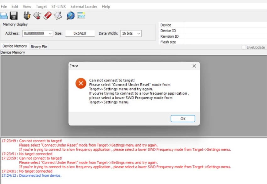
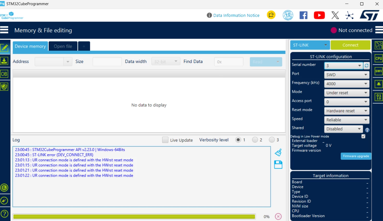
STM32F446RET6 – VCAP1 only 0.4–0.6V and MCU not detected by ST-LINK
Dear STMicroelectronics Technical Support,
I am working on a custom PCB using the STM32F446RET6 in LQFP64 package, and I am facing a hardware issue where the MCU is not detected by ST-LINK and the VCAP1 voltage is much lower than expected.
I would appreciate your help in identifying the root cause.
MCU and power configuration
- MCU: STM32F446RET6 – LQFP64
- VDD = 3.3V
- VDDA = 3.3V
- VBAT = 3.3V
- VCAP1 = Pin 30
- VSS = Pin 31 → GND
- VCAP1 capacitor = 4.7µF ceramic MLCC, 6.3V, 0603
- VCAP1 capacitor is connected between VCAP1 and GND
- NRST = 3.3V
- BOOT0 has a pull-down resistor
- SWD interface is connected to an ST-LINK debugger
Current symptoms
The 3.3V supply is stable on the MCU.
However:
- VCAP1 is only around 0.4–0.6V
- It does not remain around the expected internal core voltage
- The MCU is not detected by ST-LINK
- The same behavior occurs after replacing the MCU
Troubleshooting already performed
I have already performed the following tests:
- Checked the 3.3V supply and confirmed that VDD and VDDA are stable at 3.3V.
- Checked NRST, which is at approximately 3.3V.
- Verified the VCAP1 connection:
- Pin 30 → VCAP1
- 4.7µF capacitor → GND
- Pin 31 → GND
- Replaced the STM32F446RET6 MCU with another MCU, but the behavior remained exactly the same.
- Tried different ST-LINK/debugger connections, but the MCU is still not detected.
- Checked the PCB schematic and layout to verify the VCAP1 and power connections.
- I also compared the VCAP circuit with an ST Nucleo board.
- To eliminate the possibility of a defective VCAP capacitor, I removed the VCAP capacitor from a working Nucleo board and used that same capacitor for testing. The VCAP voltage on my custom board still remained around 0.4–0.6V.
- I also measured the resistance between VCAP1 and GND with the board powered off. On the Nucleo board I measured approximately 4 kΩ, while on my custom board the resistance is in the MΩ range.
Additional observation
The most important observation is that the 3.3V supply remains stable, while VCAP1 remains significantly lower.
Because replacing the MCU and using a known-good capacitor did not change the behavior, I am currently unsure whether the issue is related to:
- PCB routing or footprint/pin mapping
- An unintended connection on the VCAP1 net
- Power/ground configuration
- VCAP1 capacitor requirements
- Internal VCAP regulator behavior
- Another STM32F446RE power requirement that I may have missed
Request for your assistance
Could you please advise:
- What voltage should I expect on VCAP1 during power-up and normal operation for STM32F446RET6?
- Is there a recommended procedure to determine whether the internal VCAP regulator is operating correctly?
- Is the measured VCAP1-to-GND resistance useful for diagnosing this issue?
- Could the MΩ-range resistance on my custom board, compared with approximately 4 kΩ on the Nucleo, indicate a PCB connection problem?
- Are there any other power pins, decoupling requirements, or power-sequencing conditions that could cause VCAP1 to remain around 0.5V and prevent SWD/ST-LINK detection?
- Could you please review the attached schematic and PCB layout and let me know if you see anything incorrect?
I have attached the schematic, PCB layout, and relevant measurements for your review.
Thank you very much for your support. I would appreciate any recommended measurements or troubleshooting steps that can help identify the root cause before I make further changes to the PCB.