Turn on suggestions
Auto-suggest helps you quickly narrow down your search results by suggesting possible matches as you type.
Showing results for
- STMicroelectronics Community
- STM32 MCUs
- STM32 MCUs Products
- Re: SPI Clock rate limitation?
Options
- Subscribe to RSS Feed
- Mark Topic as New
- Mark Topic as Read
- Float this Topic for Current User
- Bookmark
- Subscribe
- Mute
- Printer Friendly Page
SPI Clock rate limitation?
Options
- Mark as New
- Bookmark
- Subscribe
- Mute
- Subscribe to RSS Feed
- Permalink
- Email to a Friend
- Report Inappropriate Content
2023-09-29 5:30 PM
TL;DR. What are the limiting factors for incoming clock speed for an SPI peripheral operating in slave mode?
I'm using the STM32U575 MCU with a few peripherals, and am clocking it down to 16MHz for SYSCLK and all related peripherals. I'm generating a decent amount of data by running the ADC at 20ksps. (TIM2 triggering ADC4, which drops samples into memory using DMA, and have verified output using a 1Mbaud UART.) However, what I really need is for this data to come out of the SPI peripheral, and more specifically, synced to an external clock. I figured the SPI in slave mode would be a good fit.
I've been able to get some test byte arrays out of the SPI peripheral when the SCLK line is receiving 200kHz, however, this starts falling apart at 300kHz. Falling apart means things like the TX complete callback not firing or the clock and data starting to incur some glitches.
The setup is the U575 Nucleo board, and the clock source is an external signal generator set to 3.3V square wave.
As an extra data point, I tried increasing the clock of the U575 to 160MHz (10x), and found that it works at 2MHz and stops working at 3MHz (10x jumps respectively).
Is there something within the SPI peripheral that limits the speed of the incoming clock?
Seth K
Labels:
- Labels:
-
SPI
-
STM32U5 series
15 REPLIES 15
Options
- Mark as New
- Bookmark
- Subscribe
- Mute
- Subscribe to RSS Feed
- Permalink
- Email to a Friend
- Report Inappropriate Content
2023-10-02 12:16 PM
The glitching I'm seeing is more due to my current setup. This is definitely something I will fix, but that requires making a custom PCB. I'm trying to eliminate as many fundamental issues (like that callback not being triggered) as I can before committing to a custom PCB.
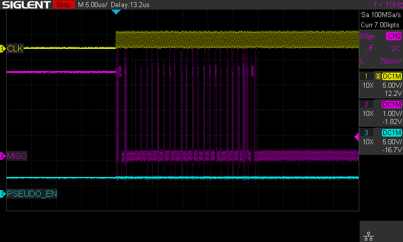
Example: 1MHz clock and the MISO line showing a good deal of overshoot along with some other noise sources coupling onto the measurement.

Seth K
Options
- Mark as New
- Bookmark
- Subscribe
- Mute
- Subscribe to RSS Feed
- Permalink
- Email to a Friend
- Report Inappropriate Content
2023-10-02 12:33 PM
i think, you should stop this useless game. :)
spi is in frames, with some sync (nss) needed, otherwise its just nonsense.

this is the spi - so to test it in any useful way, you have to send data/clk/nss in valid frames.
look at the block diagram of this spi :

what will it do, giving constant clk as slave ..? nobody knows.
with these setting i have slave receiver from esp8266, which has curious frame packets, but works fine at 16Mbit.

so try with valid spi frame format, maybe just using other spi of this chip as master.
If you feel a post has answered your question, please click "Accept as Solution".
Options
- Mark as New
- Bookmark
- Subscribe
- Mute
- Subscribe to RSS Feed
- Permalink
- Email to a Friend
- Report Inappropriate Content
2023-10-02 1:47 PM
Options
- Mark as New
- Bookmark
- Subscribe
- Mute
- Subscribe to RSS Feed
- Permalink
- Email to a Friend
- Report Inappropriate Content
2023-10-02 8:30 PM
@AScha.3 Unfortunately, I'm stuck playing this useless game.
The root cause of the problem is that I need to create a serial data stream out of an MCU which is synced to an ever-present clock. (This is for a client with a very specific design constraint, and one that I can't share :( )
I thought that either an SPI or USART peripheral would be the way to go, with the SPI being a little more malleable. I was hoping the SPI would reject the clocks if there wasn't any valid data in the buffer to send. Similarly, with the ability to SW control the NSS even in slave-mode, that seemed promising.
The SPI does seem to work with getting the data out (See prior post), but I am surprised that the callback falls apart. I expected some timing variability, but not a situation where it never gets called.
The design I thought of to counteract the clocks was to have a flip-flop on the clock net, so that I could enable/disable, but also perform a divide-by-2 if needed.
I will try running it in the proper SPI way, and see if some of these issues go away.
Seth K
Options
- Mark as New
- Bookmark
- Subscribe
- Mute
- Subscribe to RSS Feed
- Permalink
- Email to a Friend
- Report Inappropriate Content
2023-10-03 12:29 AM - edited 2023-10-03 12:31 AM
ah, more information...so not useless game here, just problematic preconditions .
so maybe you should give some information, what are the fixed preconditions :
1. fixed cont. clk at ...xxMHz ?
2. receiver can work with ...spi frame / serial uart input / - or ?
3. amount of data about ..Byte/sec . ?
4. receiver can be slave or master ?
5. distance xx m ? un-/screened cable ?
If you feel a post has answered your question, please click "Accept as Solution".
Options
- Mark as New
- Bookmark
- Subscribe
- Mute
- Subscribe to RSS Feed
- Permalink
- Email to a Friend
- Report Inappropriate Content
2023-10-04 2:36 AM - edited 2023-10-04 2:37 AM
Hello @sethkaz ,
thank you for your question.
actually you have to first resolve the MISO signal waveform after the last bit of data :

You should not have this kind of signal.
Having continuous CLK is not an issue if you are able to manage correctly NSS pin to select/unselect your slave device. If your master do not controlled correctly the NSS signal (chip select) then you will face some trouble.

Best regards
Mikael
If you feel a post has answered your question, please click Accept as Solution.
- « Previous
-
- 1
- 2
- Next »
Related Content
- I2S Clock in CubeIDE Clock Configuration seems unrelated to sample rate? in STM32CubeMX (MCUs)
- CubeMX does not split main.c into individual device files properly - Bug in STM32CubeMX (MCUs)
- STM32H563 USART clock behaviour between HSI and HSE in STM32 MCUs Boards and hardware tools
- Incorrect ADC values when using HAL setup for DISCO-L475VG-IOT01A in STM32 MCUs Embedded software
- STM32F7 Discovery kit + FMC SDRAM in STM32 MCUs Embedded software