Turn on suggestions
Auto-suggest helps you quickly narrow down your search results by suggesting possible matches as you type.
Showing results for
- STMicroelectronics Community
- STM32 MCUs
- STM32 MCUs Products
- Re: Failing to read useful data from ADC of STM32f...
Options
- Subscribe to RSS Feed
- Mark Topic as New
- Mark Topic as Read
- Float this Topic for Current User
- Bookmark
- Subscribe
- Mute
- Printer Friendly Page
Failing to read useful data from ADC of STM32f411
Options
- Mark as New
- Bookmark
- Subscribe
- Mute
- Subscribe to RSS Feed
- Permalink
- Email to a Friend
- Report Inappropriate Content
2024-01-23 09:03 AM
Hello,
upfront, it might be an incredibly dumb problem on my behalf as I am fairly new to this.
For a couple days now I have been trying to read out the voltage through the onboard ADC configured for 12 bits but all I am getting back are values in a similar range (mostly somewhere in between 1500 and 1800 but that changes with the amount of delay that I introduce, does that help?). The value itself does change, floating within that range.
I have tested for faulty connections and switched the board but the issue persists.
It is a very basic setup, just a potentiometer connected to the A0, and it works if I use an Arduino with its framework to try and read the value (the potentiometer is not broken). But also supplying A0 with ground or 3.3v directly doesn't change the read value. After reading the value I write it to serial, which is also working.
My guess is that something with my clock configuration is wrong and the ADC has not enough time to run a meaningful measurement.
I hope that any of you can help, thank in advance!
the main loop (is there any better way to format code blocks?):
while (1)
{
HAL_ADC_Start(&hadc1);
HAL_Delay(500);
HAL_ADC_PollForConversion(&hadc1, 100);
value_adc = HAL_ADC_GetValue(&hadc1);
HAL_ADC_Stop(&hadc1);
// value_adc, message and len are defined outside of the main function
sprintf(message, "value: %hu\r", value_adc);
while(CDC_Transmit_FS(message, len) != USBD_OK);
memset(message, '\0', len);
/* USER CODE END WHILE */
/* USER CODE BEGIN 3 */
}
I used CubeMx to generate the pretty much all other code, besides a tiny bit in the CDC_Receive_FS function for communication. Here is my ADC configuration:

PCLK2 is configured for 14Mhz
Solved! Go to Solution.
Labels:
- Labels:
-
ADC
-
Documentation
-
STM32CubeMX
-
STM32F4 Series
1 ACCEPTED SOLUTION
Accepted Solutions
Options
- Mark as New
- Bookmark
- Subscribe
- Mute
- Subscribe to RSS Feed
- Permalink
- Email to a Friend
- Report Inappropriate Content
2024-01-23 01:43 PM - edited 2024-01-23 01:46 PM
I was testing the other boards and while for none of them the PA0 worked, neither did PB15. I was suspicious because I could swear when I had tested that one on that specific board it had worked.
To make it short, the connection on the boards site was faulty and, regrettably the only one I hadn't thought about testing. Never going to use solderless connections ever again (that's probably not true, they are convenient).
A bit unlucky that that specific pin and all other pins that I tested from port 'A' didn't connect properly.
Anyways, thank you for your help, without it I would probably not have reconnected the boards. Everything works now!
7 REPLIES 7
Options
- Mark as New
- Bookmark
- Subscribe
- Mute
- Subscribe to RSS Feed
- Permalink
- Email to a Friend
- Report Inappropriate Content
2024-01-23 11:27 AM
It sounds like the pin you're monitoring isn't changing in value. What board is this and how is that pin hooked up? Look at the schematic to verify connectivity between pin and header. Set PA0 as an output, toggle and monitor to establish that you're monitoring what you think you are monitoring.
Unlikely to be any issues in the ADC setup.
> is there any better way to format code blocks
Click the "..." in the editor and then click "</>" to insert a code sample.
If you feel a post has answered your question, please click "Accept as Solution".
Options
- Mark as New
- Bookmark
- Subscribe
- Mute
- Subscribe to RSS Feed
- Permalink
- Email to a Friend
- Report Inappropriate Content
2024-01-23 11:30 AM - edited 2024-01-23 11:33 AM
Is the ADC enabled ?
Once it is working, increase the sampling time to >100 cycles for better accuracy
Options
- Mark as New
- Bookmark
- Subscribe
- Mute
- Subscribe to RSS Feed
- Permalink
- Email to a Friend
- Report Inappropriate Content
2024-01-23 01:05 PM - edited 2024-01-23 01:06 PM
You were correct and apparently I cannot use port 'A'? I've tested different ones and all of them do not respond. Just to make sure that the board isn't broken I tested a pin on port 'B' (specifically PB15 if that matters) and it works as expected. The onboard LED works as well. I connected an LED to the pin and set it to GPIO_Output.
I am using a blackpill with this pinout.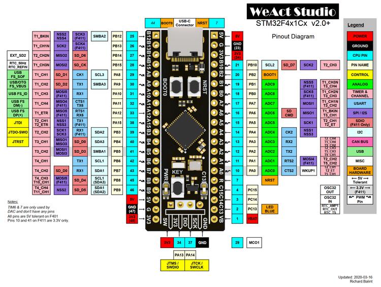 Is there maybe something special about the 'A' ports? Do I have to enable them somehow?
Options
- Mark as New
- Bookmark
- Subscribe
- Mute
- Subscribe to RSS Feed
- Permalink
- Email to a Friend
- Report Inappropriate Content
2024-01-23 01:09 PM
> Is there maybe something special about the 'A' ports? Do I have to enable them somehow?
Not really. You have to enable the clock like any other port, but GPIOA clock is enabled by default after reset and the CubeMX code should enable it anyway.
If you set PA0 (and PA1, etc..) as output and it's not able to be toggled, the hardware is bad. Most likely due to an overvoltage event.
If you feel a post has answered your question, please click "Accept as Solution".
Options
- Mark as New
- Bookmark
- Subscribe
- Mute
- Subscribe to RSS Feed
- Permalink
- Email to a Friend
- Report Inappropriate Content
2024-01-23 01:15 PM - edited 2024-01-23 01:23 PM
But I had tried three different boards (including different chips and different vendors) before coming here, all the same. I will test them again, but I doubt I will find anything conclusive.
You don't think that maybe I have a broken usb port or STLink (I am not using both at the same time) that supplies too much power practically immediately damaging the boards?
Options
- Mark as New
- Bookmark
- Subscribe
- Mute
- Subscribe to RSS Feed
- Permalink
- Email to a Friend
- Report Inappropriate Content
2024-01-23 01:31 PM
Unlikely three boards are busted, or a problem with the ST-Link. Can you get an example ADC project to run?
Can't seem to find a working schematic for that board. Some sources suggest PA0 is tied to the button.
Nucleo boards are cheap, and work. Might consider getting one of those instead.
If you feel a post has answered your question, please click "Accept as Solution".
Options
- Mark as New
- Bookmark
- Subscribe
- Mute
- Subscribe to RSS Feed
- Permalink
- Email to a Friend
- Report Inappropriate Content
2024-01-23 01:43 PM - edited 2024-01-23 01:46 PM
I was testing the other boards and while for none of them the PA0 worked, neither did PB15. I was suspicious because I could swear when I had tested that one on that specific board it had worked.
To make it short, the connection on the boards site was faulty and, regrettably the only one I hadn't thought about testing. Never going to use solderless connections ever again (that's probably not true, they are convenient).
A bit unlucky that that specific pin and all other pins that I tested from port 'A' didn't connect properly.
Anyways, thank you for your help, without it I would probably not have reconnected the boards. Everything works now!
Related Content
- The LPBAM scenario fails to be created after the HAL update. in STM32 MCUs Products
- Nucleo-STM32H753 LwIP TCP Server fails to connect to the TCP Client(Hercules) in STM32CubeMX (MCUs)
- Failing to initialize BLE on a custom STM32WB55CGU6 board in STM32 MCUs Wireless
- STM32H753 QSPI Status Flag Polling fails with Instruction on 4 lines in STM32 MCUs Products
- Failed to erase memory on Nucleo-FR446RE in STM32 MCUs Products