Turn on suggestions
Auto-suggest helps you quickly narrow down your search results by suggesting possible matches as you type.
Showing results for
- STMicroelectronics Community
- STM32 MCUs
- STM32 MCUs Motor control
- Re: Very poor current measurement when not samplin...
Options
- Subscribe to RSS Feed
- Mark Topic as New
- Mark Topic as Read
- Float this Topic for Current User
- Bookmark
- Subscribe
- Mute
- Printer Friendly Page
Very poor current measurement when not sampling mid-PWM period
Options
- Mark as New
- Bookmark
- Subscribe
- Mute
- Subscribe to RSS Feed
- Permalink
- Email to a Friend
- Report Inappropriate Content
2022-02-24 03:41 AM
STM32F405
MCSDK = V5.4.5
f_pwm = 10kHz
High frequency task = 10kHz
Medium frequency task = 1kHz
Position and speed = Hall (main) & STO+PLL (auxiliary)
Current sensing = 3 x 3mOhm shunts
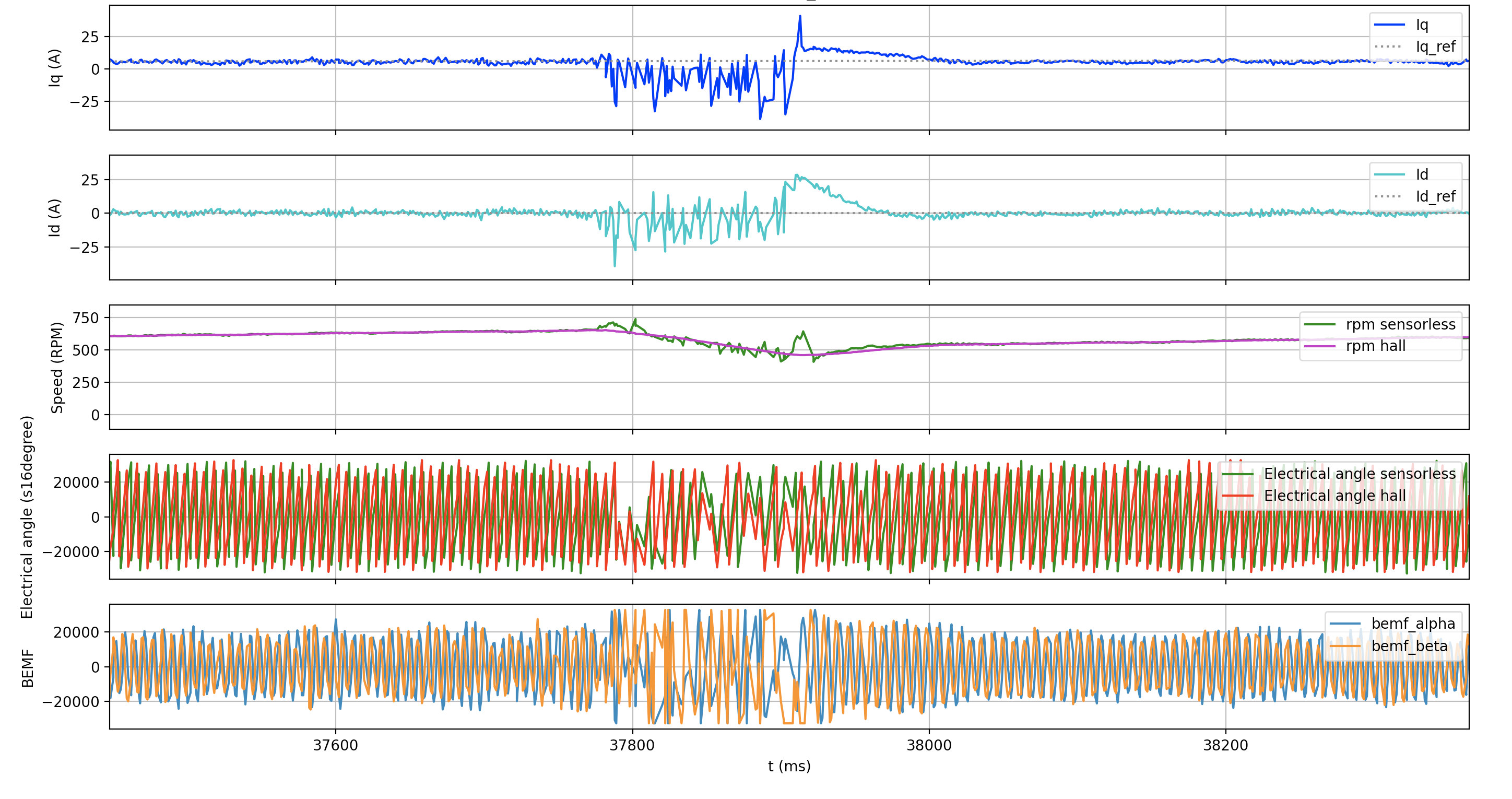
I am having a problem with very poor Id and Iq measurements when the motor hits a certain critical speed, around 650rpm mechanical with no load.
Fig1 shows plots of Iq, Id, RPM, Electrical angle (hall and sensorless) and BEMF generated by printf-ing out the values in the Medium frequency task using Segger RTT. Fig2 is the same plot but zoomed in on the "good" region. Fig3 is zoomed in on the "bad" region.
I have traced the transition between "good" and "bad" to when the R3_2_SetADCSampPointSectX() function in r3_2_f4xx_pwm.c stops sampling in the middle of the PWM period and uses one of the alternative schemes. Here are some of the defines that I believe are of interest here:
#define TNOISE_NS 1000
#define TRISE_NS 1000
#define MAX_TNTR_NS TRISE_NS
#define LOW_SIDE_SIGNALS_ENABLING LS_PWM_TIMER
#define SW_DEADTIME_NS 120
#define PWM_FREQUENCY 10000
#define PWM_FREQ_SCALING 1
I've also run a test with exactly the same motor and setup but with an alternative non-MCSDK based motor controller and this is shown in Fig4. This test does not exhibit the same problem and runs fine at over 700rpm with a much smaller variance in Iq and Id. I think this means we can rule out any issue with the motor or Hall effect sensors.
Can anyone point me to what might be the problem here?
Why might the alternative current sampling techniques be so much worse?
Is it expected that the variation in Iq and Id measurements be so large (+/-2.5A)?
EDIT:
I'm adding a link to this question (not answered yet unfortunately) which seems to describe the same problem:
Labels:
- Labels:
-
Power
-
STM32 Motor Control
-
STM32F4 Series
-
TIM
16 REPLIES 16
Options
- Mark as New
- Bookmark
- Subscribe
- Mute
- Subscribe to RSS Feed
- Permalink
- Email to a Friend
- Report Inappropriate Content
2022-03-02 11:39 AM
Options
- Mark as New
- Bookmark
- Subscribe
- Mute
- Subscribe to RSS Feed
- Permalink
- Email to a Friend
- Report Inappropriate Content
2022-03-02 11:43 AM
Is there a way to toggle an I/O pin when the ADC sample is actually taken? Then I could look with the scope to see when the current is actually sensed compared to the corresponding phase Vgs waveform
Options
- Mark as New
- Bookmark
- Subscribe
- Mute
- Subscribe to RSS Feed
- Permalink
- Email to a Friend
- Report Inappropriate Content
2022-03-03 04:51 AM
Using CubeMx, you can output the TIM1_CH4 that is linked to the sampling position:

If you agree with the answer, please accept it by clicking on 'Accept as solution'.
Best regards.
GMA
Best regards.
GMA
Options
- Mark as New
- Bookmark
- Subscribe
- Mute
- Subscribe to RSS Feed
- Permalink
- Email to a Friend
- Report Inappropriate Content
2022-03-03 10:56 AM
Ok thanks I will check that out.
Today I started looking at something else. I displayed the pwmcHandle[M1]->CntPhA
pwmcHandle[M1]->CntPhB
pwmcHandle[M1]->CntPhC
To check the waveforms. What I saw was that the max PWM duty cycle was 99.9% and the min was 0.1%. I believe this is problematic because it is possible to get into the condition where no valid current sample can be taken. To my surprise in this case the code takes the invalid sample anyway (rather than reporting an error) and hence the current measurement becomes very poor.
I had assumed that the duty cycle would be 95% max based on:
.MaxVd = (uint16_t)(MAX_MODULE * 950 / 1000),
But actually I've realised that I need to reduce the MAX_MODULE value from 32767 (100%). When I set it to 26213 (80%) the poor current readings disappear.
Of course I'm not happy with losing so much of the duty cycle to achieve that, but my understanding is that I can play around with:
- Max PWM duty cycle
- PWM frequency (currently 10kHz)
- I drive setting to mosfets (to adjust rise time, currently 1000ns)
- Deadtime (currently 400ns)
Options
- Mark as New
- Bookmark
- Subscribe
- Mute
- Subscribe to RSS Feed
- Permalink
- Email to a Friend
- Report Inappropriate Content
2022-07-26 11:33 PM
Hi I wonder you resolved this issue and found the cause of problem. If so, could you share your findings?
Sorry, I found your last update after I have posted this (it was hidden, and showed up after clicking 'more answers' button later).
Your resolution looks like sampling point always happens at the middle of PWM period by reducing max modulation percentage.
By the way, here a few comments:
- clock configuration: I think the original one is not wrong, and do not recommend to change it because many parameters are dependent on it. Especially, ADC_CLK_MHz do not support up to 84MHz (refer to datasheet)
- lowDuty: your understanding is correct. It is high_side_duty_for_lowest_low_side_duty". Though variable names are a bit confusing, but code are working correctly.
Options
- Mark as New
- Bookmark
- Subscribe
- Mute
- Subscribe to RSS Feed
- Permalink
- Email to a Friend
- Report Inappropriate Content
2022-07-27 02:53 AM
Hi THA1,
I don't have a solution other than the one I posted above:
... I've realised that I need to reduce the MAX_MODULE value from 32767 (100%). When I set it to 26213 (80%) the poor current readings disappear.
From trial and error I finally settled on a MAX_MODULE=29490. I don't really consider this a satisfactory solution, as the top end of the duty cycle range is lost, but it does prevent motor stalling.
As for your comments, I would agree with what you have said.
Options
- Mark as New
- Bookmark
- Subscribe
- Mute
- Subscribe to RSS Feed
- Permalink
- Email to a Friend
- Report Inappropriate Content
2022-07-27 05:45 PM
Thank you for your reply.
I have a similar experience at other project years ago (I falsely tested incorrect configuration which resulted in sampling point not at the middle point), but not that much significant like you case.
Now I'm developing a BLDC drive with the same environment and expect this issue sooner or later.
My opinion is to minimize sampling point deviation from the middle point:
- Max deviation from middle point = DT + max(Tnoise, Trise) + Ts
- DT, Tnoise, Trise: minimize its value (this should be guaranteed by the power board design)
- Ts: use the minimum ADC sampling cycle (need to check this might impact ADC accuracy)
- « Previous
-
- 1
- 2
- Next »
Related Content
- MotorControl Workbench Issues in STM32 MCUs Motor control
- STM32U5 ADC4: possible to enable DMA and AWD at the same time? in STM32 MCUs Products
- Is it possible to run dual motors on H7(M4 core)? in STM32 MCUs Motor control
- HSO ADC config in STM32 MCUs Motor control
- ADC Sampling Rate for STM32G431: Practical vs Theoretical measurements in STM32 MCUs Embedded software