Turn on suggestions
Auto-suggest helps you quickly narrow down your search results by suggesting possible matches as you type.
Showing results for
- STMicroelectronics Community
- STM32 MCUs
- STM32 MCUs Embedded software
- ADC Sampling Rate for STM32G431: Practical vs Theo...
Options
- Subscribe to RSS Feed
- Mark Topic as New
- Mark Topic as Read
- Float this Topic for Current User
- Bookmark
- Subscribe
- Mute
- Printer Friendly Page
ADC Sampling Rate for STM32G431: Practical vs Theoretical measurements
Options
- Mark as New
- Bookmark
- Subscribe
- Mute
- Subscribe to RSS Feed
- Permalink
- Email to a Friend
- Report Inappropriate Content
2025-01-07 11:06 PM - edited 2025-01-07 11:09 PM
Hello STM Community,
I am working with the STM32G431 microcontroller and have encountered a discrepancy between the practical and theoretical ADC sampling rates. Here's my setup:
- ADC Input: PA0 configured as ADC1_IN1 (single-ended mode).
- ADC Parameters:
- Mode: IN1 Single Ended
- ADC Prescaler: Synchronous Clock Mode Divided by 4
- Resolution: 12 bits
- Data Alignment: Right
- Continuous Conversion Mode: Enabled
- Sample Time: 2.4 ADC Cycles
- System Clock Frequency: 170 MHz
I have toggled a GPIO pin after ADC conversion to observe the sampling rate on an oscilloscope. The measured sampling rate is approximately 142 kHz, while my theoretical calculation suggests it should be around 11.33 MHz.
The theoretical calculation considers the formula:
Sampling Rate=fADC /{ [sampling time(in cycles)] + [resolution (in bits)] +(0.5)}
Substituting the values:
Sampling Rate=170 MHz / (2.4+12+0.5) ≈ 11.33 MHz
I am unable to identify why there is such a significant difference between the calculated and observed rates. Could it be due to additional overhead, configuration issues, or something else I'm overlooking?
Any insights or suggestions to help resolve this would be greatly appreciated!
Thank you!
Labels:
- Labels:
-
ADC
-
Interrupt
-
STM32G4 Series
-
TIM
13 REPLIES 13
Options
- Mark as New
- Bookmark
- Subscribe
- Mute
- Subscribe to RSS Feed
- Permalink
- Email to a Friend
- Report Inappropriate Content
2025-01-08 12:02 AM
Hi,
1. how you get the idea, the ADC would convert at 11MHz speed ?
Look at ds : absolute max. speed at 12bits is 4 Mhz :

2. The ADC is clocked, so it will convert at the speed you set it - not only theoretical .
Now your measured speed is a bit slow, so you set it very wrong.
3. Read ds + manual , to see how to use it. And dont forget calibration .
Or look at examples from STM , and app.notes ANxxx , to see, how to use it.
If you feel a post has answered your question, please click "Accept as Solution".
Options
- Mark as New
- Bookmark
- Subscribe
- Mute
- Subscribe to RSS Feed
- Permalink
- Email to a Friend
- Report Inappropriate Content
2025-01-08 12:34 AM
I agree that theoretical calculation may be wrong!.
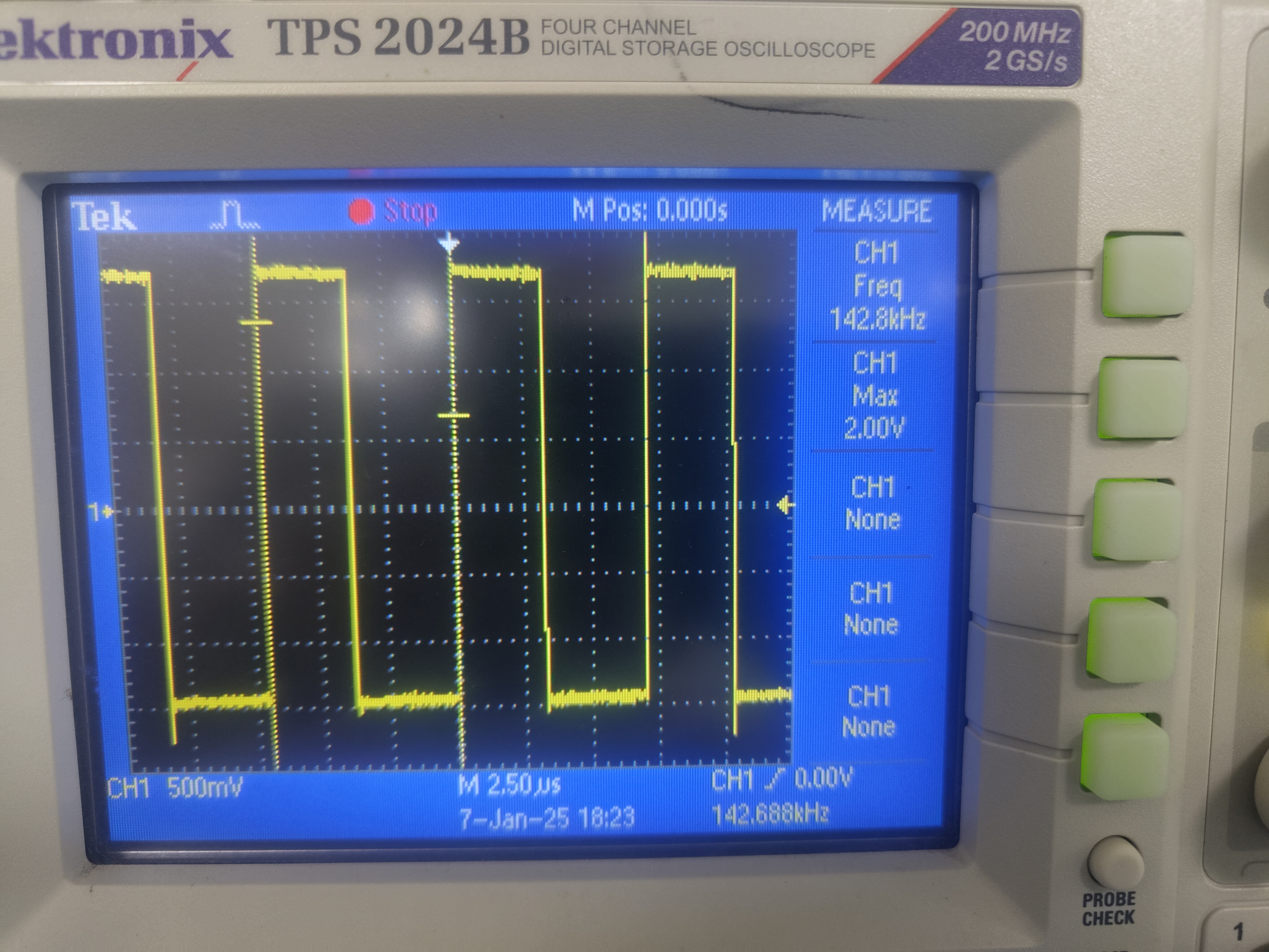
Now as you the waveforms GPIO in the interrupt is toggling at the 142,8Khz attached image.
System clock is 170Mhz
- Mode: IN1 Single Ended
- Clock Prescaler: Synchronous Clock Mode Divided by 4
- Resolution: 12 bits
- Data Alignment: Right
- Continuous Conversion Mode: Enabled
- Sample Time: 2.5 Cycles
please help in understanding how I got this 142.8Khz
Options
- Mark as New
- Bookmark
- Subscribe
- Mute
- Subscribe to RSS Feed
- Permalink
- Email to a Friend
- Report Inappropriate Content
2025-01-08 12:37 AM
please share me the app note links or forum links.
Thanks
Options
- Mark as New
- Bookmark
- Subscribe
- Mute
- Subscribe to RSS Feed
- Permalink
- Email to a Friend
- Report Inappropriate Content
2025-01-08 12:51 AM
>please help in understanding how I got this 142.8Khz
Well, i cannot know, what you doing...
so at first check, is your system running at xx speed : use MCO pin, set it to main clk /10 , or whatever, and look with a scope on MCO then; just to verify ,your cpu is running that speed, you expect .
Then look at ADC clock: what you set , going to ADC module ?
Then check, whats you do with ADC (read in manual...) , set to the mode (group conversion, single conversion etc.);
and the sampling time you set (dont use 2.5 , except your source is very low impedance; set 6.5 or 12.5 ).
-> calculate speed from ADC clock (/ divider) (/ sampling_time + 12.5 conversion_time) -> maybe:
-> 30MHz / 25 = 1.2 MHz . check it with your bit toggling.
If you feel a post has answered your question, please click "Accept as Solution".
Options
- Mark as New
- Bookmark
- Subscribe
- Mute
- Subscribe to RSS Feed
- Permalink
- Email to a Friend
- Report Inappropriate Content
2025-01-08 12:56 AM - edited 2025-01-08 2:16 AM
app notes ...see at STM :
ed. ->
https://www.st.com/en/microcontrollers-microprocessors/stm32g431rb.html#documentation


+ for forum links : you can try search function yourself ...
If you feel a post has answered your question, please click "Accept as Solution".
Options
- Mark as New
- Bookmark
- Subscribe
- Mute
- Subscribe to RSS Feed
- Permalink
- Email to a Friend
- Report Inappropriate Content
2025-01-08 1:01 AM
Hello @krushna_moukthik ,
Ensure that the ADC is properly calibrated, this helps reduce offset, gain errors and can affect the accuracy of the sampling rate.
You can refer to these application notes:
- STM32G4 ADC use tips and recommendations - Application note
- How to optimize the ADC accuracy in the STM32 MCUs - Application note
- How to use ADC Oversampling techniques to improve signal-to-noise ratio on STM32 MCUs - Application note
When your question is answered, please close this topic by clicking "Accept as Solution".
Thanks
Imen
Thanks
Imen
Options
- Mark as New
- Bookmark
- Subscribe
- Mute
- Subscribe to RSS Feed
- Permalink
- Email to a Friend
- Report Inappropriate Content
2025-01-08 1:28 AM
Hello
I am also facing the same issue in the same board :D , my code looks like
while (1)
{
HAL_ADC_Start_IT(&hadc1);
HAL_GPIO_WritePin(PA9_GPIO_Port, PA9_Pin, GPIO_PIN_SET);
}

void HAL_ADC_ConvCpltCallback(ADC_HandleTypeDef *hadc)
{
HAL_GPIO_WritePin(PA9_GPIO_Port, PA9_Pin, GPIO_PIN_RESET);
adcBuffer = HAL_ADC_GetValue(&hadc1);
}
ADC : 12 bit, single ended, 60Mhz(sychronous), ADC1 - IN1, 2.5 cycles sampling time, Fast channel
theoretically, it should be 250ns, but i am getti ng 2590ns

Options
- Mark as New
- Bookmark
- Subscribe
- Mute
- Subscribe to RSS Feed
- Permalink
- Email to a Friend
- Report Inappropriate Content
2025-01-08 2:05 AM - edited 2025-01-08 2:06 AM
So please open a new thread with your question, not capture others ...
If you feel a post has answered your question, please click "Accept as Solution".
Options
- Mark as New
- Bookmark
- Subscribe
- Mute
- Subscribe to RSS Feed
- Permalink
- Email to a Friend
- Report Inappropriate Content
2025-01-08 7:03 AM
First, you've missed :
Sampling Rate=fADC /{ [sampling time(in cycles)] + [resolution (in bits)] +(0.5)}
Substituting the values:
Sampling Rate=(170 MHz /ADC Prescaler: Synchronous Clock Mode Divided by 4)/ (2.4+12+0.5) ≈ 11.33 MHz
Second don't use interrupt , better way to verify sampling is to set array for adc samples and feed pwm with known frequency (confirmed with o-scope) to adc input.
Related Content
- New book on STM32F10x Microcontrollers (English and French) in Others: STM32 MCUs related
- STM32F0 + HSE Crystal: Confusion on Rext (Harmonic Suppression vs Reliable Startup) in STM32 MCUs Products
- STM32WB5MMG Current Consumption in STOP2 Mode with RTC Enabled in STM32 MCUs Wireless
- Can the STM32U5 converge to an efficient algorithm, or a few, to enter to low power? in STM32 MCUs Products