Turn on suggestions
Auto-suggest helps you quickly narrow down your search results by suggesting possible matches as you type.
Showing results for
- STMicroelectronics Community
- Automotive & Transportation
- Microcontrollers
- Re: Wake up Example Question.
Options
- Subscribe to RSS Feed
- Mark Topic as New
- Mark Topic as Read
- Float this Topic for Current User
- Bookmark
- Subscribe
- Mute
- Printer Friendly Page
Wake up Example Question.
Options
- Mark as New
- Bookmark
- Subscribe
- Mute
- Subscribe to RSS Feed
- Permalink
- Email to a Friend
- Report Inappropriate Content
2023-04-12 02:46 AM
I am currently reviewing examples of the phrase 'WKPU'.
Example is "SPC58xHxx_cut2_RLA WKPU Interrupt Test Application for Discovery".
If you press button sw0, LED3 turns on.
If you press button sw1, LED1 turns on.
And if you press button sw2, LED2 turns on.
What I'm curious about.
void wkpu0_int12_cb(WKPUDriver *wkpup);
I'm curious about how the function is linked to the sw1 button. Can you explain that?
Likewise....
void wkpu0_int18_cb(WKPUDriver *wkpup);
I'm curious about how the function is linked to the sw2 button. Can you explain that?
And..
void wkpu0_int18_cb(WKPUDriver *wkpup);
I'm curious about how the function is linked to the sw3 button. Can you explain that?
In conclusion, it's all the same question....
help me ㅠㅠ
Solved! Go to Solution.
Labels:
- Labels:
-
SPC5 Automotive MCUs
1 ACCEPTED SOLUTION
Accepted Solutions
Options
- Mark as New
- Bookmark
- Subscribe
- Mute
- Subscribe to RSS Feed
- Permalink
- Email to a Friend
- Report Inappropriate Content
2023-05-09 07:37 PM
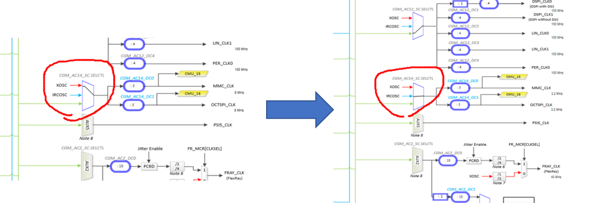
I've solved this problem.
CGM_AC14_SC.SELCTRL of Clock tree change XOSC to IRCOSC.
like attached file.
9 REPLIES 9
Options
- Mark as New
- Bookmark
- Subscribe
- Mute
- Subscribe to RSS Feed
- Permalink
- Email to a Friend
- Report Inappropriate Content
2023-04-12 05:52 AM
Hi hasumi,
you deserve a better answer than the last one from chatGPT.
issue whit chatGPT is that answer seems coherent, but all details are false.
Please let me a little more time to answer to your one question:
"void wkpu0_int18_cb(WKPUDriver *wkpup);
I'm curious about how the function is linked to the sw button. Can you explain that?"
then you will extrapole for your smae last questions.
see you soon for the true answer and
Best Regards
Options
- Mark as New
- Bookmark
- Subscribe
- Mute
- Subscribe to RSS Feed
- Permalink
- Email to a Friend
- Report Inappropriate Content
2023-04-12 08:40 AM - edited 2023-11-20 08:27 AM
Open the board User Manual UM2697:

You can see that push button 1 (PB1) is connected to MCU port PA2.
In SPC5Studio, open the Pinmap Wizard in your application:

You can see that MCU port PA2 is configured as interrupt input WPKU0_INT18.
Open the Reference Manual RM0452 and look to table 51:

You can see that WAKPU0 module interrupt WKUP18 is mapped on WKPU_0_IRQ_2.
Then look on table 37:

You can see that WKPU0 IRQ2 is mapped to MCU External Interrupt 249.
In our header spc58xh_registry.h :
#define SPC5_WKPU0_IRQ2_HANDLER vector249
In our low level driver wkpu_lld.c :
IRQ_HANDLER(SPC5_WKPU0_IRQ2_HANDLER) {
…
WKPUD1.config->wk_config[i + 16U]->irq_cb(&WKPUD1);
…
}
When interrupt occurs, the driver WKPUD1 is calling the call-back irq_cb registered in wk_config.
This is why in our main function we configure WKPUD1:
wkpu_lld_start(&WKPUD1, &wkpu_config_wkpu0);
wkpu_config_wkpu0. wk_config [18] is configured with wkpu_config_wkpu0_wk_INT18
and wkpu_config_wkpu0_wk_INT18.irq_cb is configured with call-back wkpu0_int18_cb which is defined in our demo main.c
Best Regards.
Options
- Mark as New
- Bookmark
- Subscribe
- Mute
- Subscribe to RSS Feed
- Permalink
- Email to a Friend
- Report Inappropriate Content
2023-04-12 08:47 AM - edited 2023-11-20 08:27 AM
So according to the code, when pushing on Button1, You should toggle the LED2 mapped on MCU port PI[12] 
This is not in line with demo README file...
Options
- Mark as New
- Bookmark
- Subscribe
- Mute
- Subscribe to RSS Feed
- Permalink
- Email to a Friend
- Report Inappropriate Content
2023-04-17 02:32 AM
Thank you for explaining the above problem so well that I understand it. Thank you.
One more question related to the wake up example!
It's about examples.-> "SPC58xHxx_cut2_RLA_WKPU Test Application for Discovery"
When I run the example, it worked successfully.
When the RUNMODE of SPC5 is set to STOP0 and the SW_1 button is pressed, the board successfully transitions back to RUN mode.
I created a project to replicate the same behavior, but the SW_1 button press did not transition the mode to RUN as expected..
Is there anything that needs to be configured to make the SW_1 button transition the mode to RUN?
I compared the example code with my project and made the necessary configurations. If there are any other areas I should check, please let me know....
Options
- Mark as New
- Bookmark
- Subscribe
- Mute
- Subscribe to RSS Feed
- Permalink
- Email to a Friend
- Report Inappropriate Content
2023-04-18 08:16 AM - edited 2023-11-20 08:27 AM
Hello,
maybe you forgot to activate de wakeup request in Low Level Driver configuration ?

Best Regard.
Options
- Mark as New
- Bookmark
- Subscribe
- Mute
- Subscribe to RSS Feed
- Permalink
- Email to a Friend
- Report Inappropriate Content
2023-04-19 06:13 PM
Options
- Mark as New
- Bookmark
- Subscribe
- Mute
- Subscribe to RSS Feed
- Permalink
- Email to a Friend
- Report Inappropriate Content
2023-04-19 11:54 PM
Humm not really unfortunately...
may be check you have this code in main .c:
void int18_irq_cb(WKPUDriver *wkpup)
{
(void)wkpup;
/* Wait the SIUL2 is ready after
the exit from the SPOP0 mode.*/
while (MC_ME.PS0.B.S_SIUL == 0U) {
;
}
pal_lld_setpad(PORT_I, PI_LED2);
}
this in main function:
wkpu_lld_start(&WKPUD1, &wkpu_config_wkpu_cfg);
this in wkpu_lld_cfg.c:
WKPUConfig wkpu_config_wkpu_cfg = {
{
NULL,
NULL,
NULL,
NULL
},
{
NULL,//0
NULL,//1
NULL,//2
NULL,//3
NULL,//4
NULL,//5
NULL,//6
NULL,//7
NULL,//8
NULL,//9
NULL,//10
NULL,//11
NULL,//12
NULL,//13
NULL,//14
NULL,//15
NULL,//16
NULL,//17
&wkpu_config_wkpu_cfg_wk_INT18,//18
NULL,
NULL,
NULL,
NULL,
NULL,
NULL,
NULL,
NULL,
NULL,
NULL,
NULL,
NULL,
NULL,
}
};
and
WakeupConfig wkpu_config_wkpu_cfg_wk_INT18 = {
TRUE,
TRUE,
int18_irq_cb,
FALSE,
TRUE,
TRUE,
FALSE
};
Options
- Mark as New
- Bookmark
- Subscribe
- Mute
- Subscribe to RSS Feed
- Permalink
- Email to a Friend
- Report Inappropriate Content
2023-04-24 02:00 AM
Unfortunately....
I copied and pasted the code you provided, but it didn't work as expected. Thank you for your response.
Options
- Mark as New
- Bookmark
- Subscribe
- Mute
- Subscribe to RSS Feed
- Permalink
- Email to a Friend
- Report Inappropriate Content
2023-05-09 07:37 PM
Related Content
- About int18 in sample code spc58ec wkpu in Microcontrollers
- Pin mode question for SPC582B using SPC5 Studio in AutoDevKit Ecosystem
- Teseo III changing baud rate and a hopefully basic question in GNSS positioning
- Hello! I want to ask a question about setting up EIRQ! in AutoDevKit Ecosystem
- [AEK-MCU-C4MLIT1] Error in UART and Illegal instruction fetched at address 0x400a8030 in OpenOCD in AutoDevKit Ecosystem