Turn on suggestions
Auto-suggest helps you quickly narrow down your search results by suggesting possible matches as you type.
Showing results for
- STMicroelectronics Community
- STM32 MCUs
- STM32 MCUs Products
- USART1 interrupt handler not called
Options
- Subscribe to RSS Feed
- Mark Topic as New
- Mark Topic as Read
- Float this Topic for Current User
- Bookmark
- Subscribe
- Mute
- Printer Friendly Page
USART1 interrupt handler not called
Options
- Mark as New
- Bookmark
- Subscribe
- Mute
- Subscribe to RSS Feed
- Permalink
- Email to a Friend
- Report Inappropriate Content
2023-08-18 5:36 AM - edited 2023-08-18 5:40 AM
Hello,
first, I'm new to STM32 Nucleo MCUs, so if I am asking something that is well-known in documentation of Nucelo boards please advise me to correct documentation.
I have a project using a STM32 L432KC that gets serial data from another MCU and sendsdata iuzt via CAN and UART2.
The project is configured with using UART interrupt mode (on both UART1/2). If I check serial data without connected STM32, the data is correctly send from other MCU (configured with baud rate 115200) and also on STM side UART1 is configured with 115200 baud rate:
static void MX_USART1_UART_Init(void)
{

  /* USER CODE BEGIN USART1_Init 0 */
  /* USER CODE END USART1_Init 0 */

  /* USER CODE BEGIN USART1_Init 1 */
  /* USER CODE END USART1_Init 1 */
  huart1.Instance = USART1;
  huart1.Init.BaudRate = 115200;
  huart1.Init.WordLength = UART_WORDLENGTH_8B;
  huart1.Init.StopBits = UART_STOPBITS_1;
  huart1.Init.Parity = UART_PARITY_NONE;
  huart1.Init.Mode = UART_MODE_TX_RX;
  huart1.Init.HwFlowCtl = UART_HWCONTROL_NONE;
  huart1.Init.OverSampling = UART_OVERSAMPLING_16;
  huart1.Init.OneBitSampling = UART_ONE_BIT_SAMPLE_DISABLE;
  huart1.AdvancedInit.AdvFeatureInit = UART_ADVFEATURE_NO_INIT;
  if (HAL_UART_Init(&huart1) != HAL_OK)
  {
    Error_Handler();
  }
  /* USER CODE BEGIN USART1_Init 2 */
  /* USER CODE END USART1_Init 2 */

}
UART1 is configured to output pins PA9 (Serial1 TX) and PA10 (Serial1 RX), both connected to serial output from other MCU. If I check without STM MCU, all data is correctly sent from this MCU (as I can check with serial terminal connection). But as soon as I connect with STM, serial data flow stops from other MCU, no other data is seen if I connect serial cable to pins PA9/10 mentioned above.
For init of STM HAL functions are used as documented with normal interrupt mode for UART1:
int main(void)
{
  /* USER CODE BEGIN 1 */
  HAL_DeInit();

  /* USER CODE END 1 */

  /* MCU Configuration--------------------------------------------------------*/

  /* Reset of all peripherals, Initializes the Flash interface and the Systick. */
  HAL_Init();

  /* USER CODE BEGIN Init */

  /* USER CODE END Init */

  /* Configure the system clock */
  SystemClock_Config();

  /* USER CODE BEGIN SysInit */
  /* USER CODE END SysInit */

  /* Initialize all configured peripherals */
  MX_GPIO_Init();
  MX_USART2_UART_Init();
  MX_CAN1_Init();
  MX_USART1_UART_Init();
  /* USER CODE BEGIN 2 */
...

  //Activate UART interrupt
  HAL_UART_Receive_IT(&huart1, RxData, sizeof(RxData));
...
and in RxCallback function several checks for incoming data are made:
void HAL_UART_RxCpltCallback(UART_HandleTypeDef *huart)								//if STM32 receives Data
{
	HAL_UART_Receive_IT(&huart1, RxData, sizeof(RxData));

	if (RxData[2] == 0x37) {
		if (RxData[3] == 0x37) {
			reset = 1;
			return;
		}
	}

	if (RxData[0] == '0')
	{
		return;
	}

	printf("%d%d\r\n", RxData[0], RxData[1]);

	if (isCMD(RxData)) transmit = 1;
}
If I debug STM code and trigger data transmit from other MCU, the RxCallback function never gets triggered, so my question is, am I doing something wrong?
Note: I'm using CubeIDE 1.13.0
Thanks for any hints & suggestions,
Lorky
Labels:
- Labels:
-
Interrupt
-
LPUART
-
STM32L4 series
This discussion is locked. Please start a new topic to ask your question.
9 REPLIES 9
Options
- Mark as New
- Bookmark
- Subscribe
- Mute
- Subscribe to RSS Feed
- Permalink
- Email to a Friend
- Report Inappropriate Content
2023-08-18 5:45 AM - edited 2023-08-18 5:51 AM
Hello @lorky ,
did you enable the interrupt ?
I suggest you check this article : How to use register callbacks in STM32? - STMicroelectronics Community
also you can check the available examples in the stm32cubefw :STM32Cube_FW_L4_V1.17.2\Projects\NUCLEO-L432KC\Examples\UART
Foued
To give better visibility on the answered topics, please click on Accept as Solution on the reply which solved your issue or answered your question.
Options
- Mark as New
- Bookmark
- Subscribe
- Mute
- Subscribe to RSS Feed
- Permalink
- Email to a Friend
- Report Inappropriate Content
2023-08-18 7:20 AM - edited 2023-08-18 7:22 AM
> But as soon as I connect with STM, serial data flow stops from other MCU, no other data is seen if I connect serial cable to pins PA9/10 mentioned above.
How exactly do you connect the cable? Where on Nucleo do you connect the wire on which you've observed the transmission from other mcu?
Do you connect grounds?
In debugger, read out and check/post content of related GPIO pins. In Nucleo documentation (manual, schematics) check, if given pins are connected to expected headers and are not connected to on-board resources such as the STLink VCP (mainly check solder bridges (SBxx) and jumpers).
Also, try transmitting from STM32 (in blocking mode) and observing it on the USART1_TX pin.
JW
Options
- Mark as New
- Bookmark
- Subscribe
- Mute
- Subscribe to RSS Feed
- Permalink
- Email to a Friend
- Report Inappropriate Content
2023-08-18 8:45 AM
The USART1 interrupt must be enabled in the NVIC, and the vector table routine, nominally USART1_IRQHandler() needs to be calling into the HAL processing and dispatch method.
/**
  * @brief This function handles USART1 global interrupt.
  */
void USART1_IRQHandler(void)
{
  HAL_UART_IRQHandler(&huart1);
}
Tips, Buy me a coffee, or three.. PayPal Venmo
Up vote any posts that you find helpful, it shows what's working..
Up vote any posts that you find helpful, it shows what's working..
Options
- Mark as New
- Bookmark
- Subscribe
- Mute
- Subscribe to RSS Feed
- Permalink
- Email to a Friend
- Report Inappropriate Content
2023-08-20 12:21 PM
huart1.Init.WordLength = UART_WORDLENGTH_8B;
  huart1.Init.StopBits = UART_STOPBITS_1;
Means 7 databits and 1 stop bit, are you sure this is what you want as settings?
ST has a special way at counting databits.
If parity or stop bit settings are wrong, error fault handlers are called, have you tried putting breakpoints at these handlers or implementing your own?
Options
- Mark as New
- Bookmark
- Subscribe
- Mute
- Subscribe to RSS Feed
- Permalink
- Email to a Friend
- Report Inappropriate Content
2023-08-20 12:36 PM
>>Means 7 databits and 1 stop bit, are you sure this is what you want as settings?
No it doesn't..
Parity bits might be counted but stop bits aren't.
Tips, Buy me a coffee, or three.. PayPal Venmo
Up vote any posts that you find helpful, it shows what's working..
Up vote any posts that you find helpful, it shows what's working..
Options
- Mark as New
- Bookmark
- Subscribe
- Mute
- Subscribe to RSS Feed
- Permalink
- Email to a Friend
- Report Inappropriate Content
2023-08-31 7:32 AM - edited 2023-08-31 7:32 AM
Hi @Foued_KH ,
thanks for your reply, sorry for late answer as I was on vacation last week (writing this from py private account...)
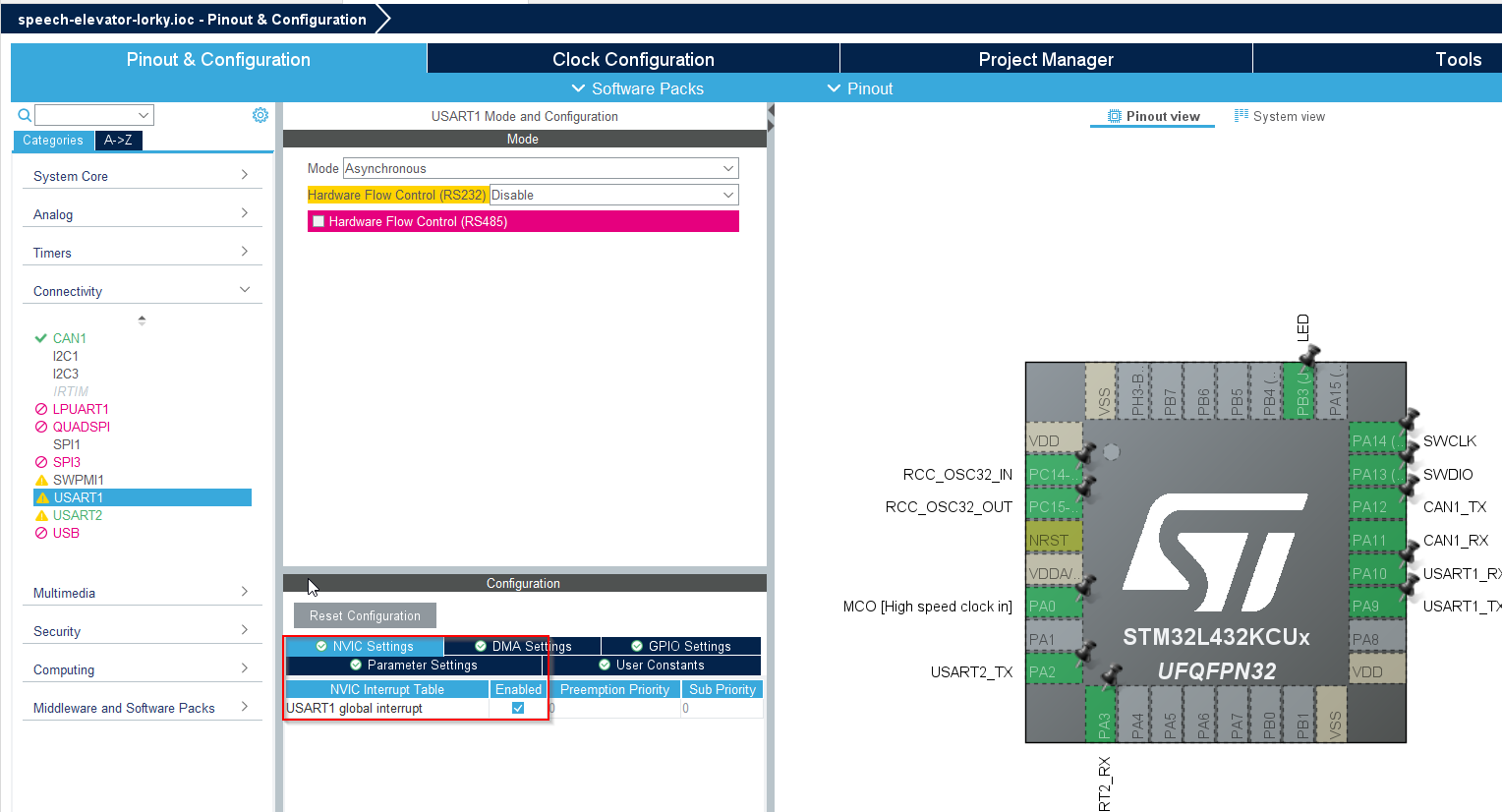
Yes, I did enable global interrupt for relevant USART1 (please see screenshot below):. I think interrupt is working as if I do manual sending of chars from Putty serial terminal I do get interrupt trigger after 4 chars (please see debugger session and connected serial cable to TX/RX pins from STM)
Thank you & BR
Lorky
Options
- Mark as New
- Bookmark
- Subscribe
- Mute
- Subscribe to RSS Feed
- Permalink
- Email to a Friend
- Report Inappropriate Content
2023-08-31 7:39 AM
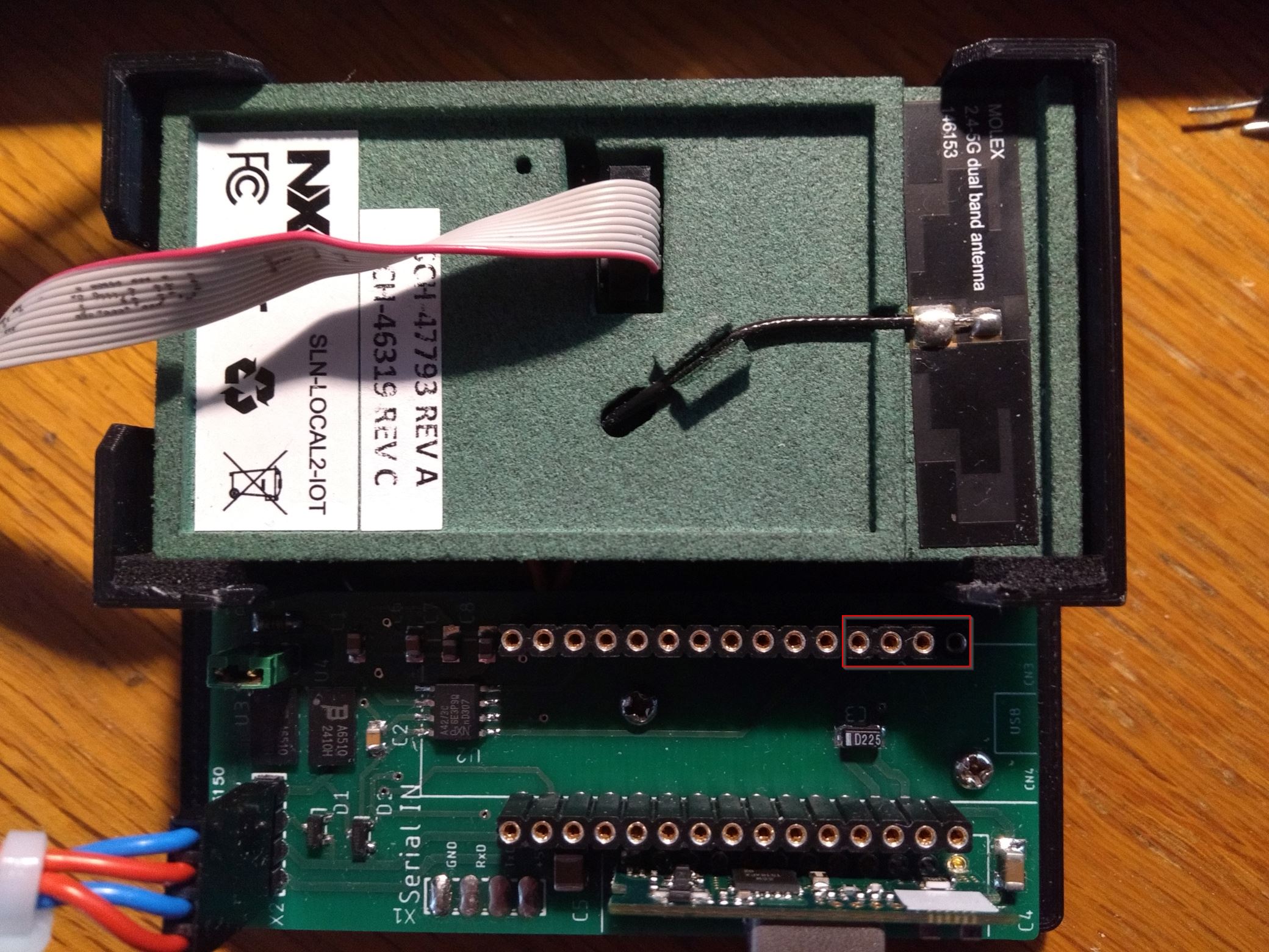
Hi @waclawek.jan ,
thank you for your reply. The TX/RX pins from both MCUs are connected (soldered) with cable, STM MCU is in socket (please see pictures below, so NXP MCU RX pin is conected to PA_9 (Serial1_TX), NXP TX pin is connected to PA_10 (Serial1_RX).
My assumption was that if I connect serial cable on pin header on top side of STM MCU I get the same signals as they are at bottom side of STM MCU (in my configuration socketed) (please see picture for pins from serial cable at top side of STM MCU).
I did not explicitly check grounds but as this hardware did work with other software in the past I suppose grounds are correctly connected.
Sorry I did not understand your paragraph with related GPIO pins, Is this configuration in generated code from project generator, as I do not see any function in my main.c file with this content.
With transmitting from STM32 you mean connection from STM -> NXP controller, right? I did not check this, but do not need this data direction, I only need NXP->STM connection, but I can try if this works.
Thanks & BR
Lorky
Options
- Mark as New
- Bookmark
- Subscribe
- Mute
- Subscribe to RSS Feed
- Permalink
- Email to a Friend
- Report Inappropriate Content
2023-08-31 7:43 AM
Hi @Tesla DeLorean ,
thanks for your reply. I did not find this function in my generated project. I suppose this is in HAL section of STM generated code, right? Should this not be done automatically if I enable global interrupt for USART1 in "Pinout & Configuration part of CubeIDE)?
Thanks & BR,
Lorky
Options
- Mark as New
- Bookmark
- Subscribe
- Mute
- Subscribe to RSS Feed
- Permalink
- Email to a Friend
- Report Inappropriate Content
2023-08-31 8:22 AM
> Sorry I did not understand your paragraph with related GPIO pins, Is this configuration in generated code from project generator, as I do not see any function in my main.c file with this content.
Do you use a debugger, such as the one built into CubeIDE? If yes, then you have somewhere a "peripheral view" or "SFR view" or similarly named window; in it, you can observe content of GPIOA registers and check them against Reference Manual (RM) or post them here.
JW
Related Content
- NUCLEO-H533RE USB DFU Software method in STM32 MCUs Products
- STM32H750: unexpected behaviour when trying to send multi-packet messages over USB in STM32 MCUs Embedded software
- Debugging QSPI XiP with VS Code on STM32H750B-DK in STM32CubeIDE for Visual Studio Code (MCUs)
- how to use RTX5 with Root of Trust on NUCLEO-N657X0-Q ? in STM32 MCUs Security
- STM32G4 UART Signal Handler Error in STM32 MCUs Products