UART communication
- Mark as New
- Bookmark
- Subscribe
- Mute
- Subscribe to RSS Feed
- Permalink
- Email to a Friend
- Report Inappropriate Content
2024-01-18 2:13 AM - last edited on 2024-01-19 4:38 AM by Imen.D
Hello everyone, I am trying to make a UART Communication between STM32 NUCLEO-L476RG and ESP32 S3. The STM must send data to ESP and the ESP must print it on Serial Monitor of Arduino IDE.
However, this doesn't happen, even though I have double checked the connections. The code for the same are given below :-
STM32 NUCLEO-L476RD board code:-
#include "stm32f4xx_hal.h"
UART_HandleTypeDef huart2;
void SystemClock_Config(void);
static void MX_GPIO_Init(void);
static void MX_USART2_UART_Init(void);
int main(void)
{
HAL_Init();
SystemClock_Config();
MX_GPIO_Init();
MX_USART2_UART_Init();
char data_to_send[] = "Hello, PC!";
while (1)
{
HAL_UART_Transmit(&huart2, (uint8_t *)data_to_send, strlen(data_to_send), HAL_MAX_DELAY);
HAL_Delay(1000); // Delay for 1 second (adjust as needed)
}
}
void SystemClock_Config(void)
{
RCC_OscInitTypeDef RCC_OscInitStruct = {0};
RCC_ClkInitTypeDef RCC_ClkInitStruct = {0};
__HAL_RCC_PWR_CLK_ENABLE();
__HAL_PWR_VOLTAGESCALING_CONFIG(PWR_REGULATOR_VOLTAGE_SCALE1);
RCC_OscInitStruct.OscillatorType = RCC_OSCILLATORTYPE_HSI;
RCC_OscInitStruct.HSIState = RCC_HSI_ON;
RCC_OscInitStruct.HSICalibrationValue = RCC_HSICALIBRATION_DEFAULT;
RCC_OscInitStruct.PLL.PLLState = RCC_PLL_ON;
RCC_OscInitStruct.PLL.PLLSource = RCC_PLLSOURCE_HSI;
RCC_OscInitStruct.PLL.PLLM = 16;
RCC_OscInitStruct.PLL.PLLN = 336;
RCC_OscInitStruct.PLL.PLLP = RCC_PLLP_DIV4;
RCC_OscInitStruct.PLL.PLLQ = 7;
if (HAL_RCC_OscConfig(&RCC_OscInitStruct) != HAL_OK)
{
Error_Handler();
}
if (HAL_PWREx_EnableOverDrive() != HAL_OK)
{
Error_Handler();
}
RCC_ClkInitStruct.ClockType = RCC_CLOCKTYPE_HCLK | RCC_CLOCKTYPE_SYSCLK |
RCC_CLOCKTYPE_PCLK1 | RCC_CLOCKTYPE_PCLK2;
RCC_ClkInitStruct.SYSCLKSource = RCC_SYSCLKSOURCE_PLLCLK;
RCC_ClkInitStruct.AHBCLKDivider = RCC_SYSCLK_DIV1;
RCC_ClkInitStruct.APB1CLKDivider = RCC_HCLK_DIV4;
RCC_ClkInitStruct.APB2CLKDivider = RCC_HCLK_DIV2;
if (HAL_RCC_ClockConfig(&RCC_ClkInitStruct, FLASH_LATENCY_5) != HAL_OK)
{
Error_Handler();
}
}
static void MX_USART2_UART_Init(void)
{
huart2.Instance = USART2;
huart2.Init.BaudRate = 115200;
huart2.Init.WordLength = UART_WORDLENGTH_8B;
huart2.Init.StopBits = UART_STOPBITS_1;
huart2.Init.Parity = UART_PARITY_NONE;
huart2.Init.Mode = UART_MODE_TX_RX;
huart2.Init.HwFlowCtl = UART_HWCONTROL_NONE;
huart2.Init.OverSampling = UART_OVERSAMPLING_16;
if (HAL_UART_Init(&huart2) != HAL_OK)
{
Error_Handler();
}
}
static void MX_GPIO_Init(void)
{
__HAL_RCC_GPIOA_CLK_ENABLE();
GPIO_InitTypeDef GPIO_InitStruct = {0};
GPIO_InitStruct.Pin = GPIO_PIN_2 | GPIO_PIN_3;
GPIO_InitStruct.Mode = GPIO_MODE_AF_PP;
GPIO_InitStruct.Pull = GPIO_NOPULL;
GPIO_InitStruct.Speed = GPIO_SPEED_FREQ_HIGH;
GPIO_InitStruct.Alternate = GPIO_AF7_USART2;
HAL_GPIO_Init(GPIOA, &GPIO_InitStruct);
}
void Error_Handler(void)
{
while (1)
{
// Error handling
}
}
#ifdef USE_FULL_ASSERT
void assert_failed(uint8_t *file, uint32_t line)
{
// User can add their own implementation to report the file name and line number,
// ex: printf("Wrong parameters value: file %s on line %d\r\n", file, line)
}
#endif
ESP32 S3 WROOM 1 code:-
void setup() {
Serial.begin(115200, SERIAL_8N1); // Set baud rate, data bits, no parity, and 1 stop bit
}
void loop() {
if (Serial.available() > 0) {
char incomingByte = Serial.read();
Serial.print("Received: ");
Serial.println(incomingByte);
}
delay(1000);
}
- Labels:
-
STM32L4 series
-
UART-USART
- Mark as New
- Bookmark
- Subscribe
- Mute
- Subscribe to RSS Feed
- Permalink
- Email to a Friend
- Report Inappropriate Content
2024-01-18 2:19 AM - edited 2024-01-18 2:20 AM
Sounds like a homework assignment.
Draw a schematic of how this is wired up.
Check signals with a scope. Perhaps send "UUUU" pattern continously.
Make sure you have the RX and TX sense correct, and a common ground.
Up vote any posts that you find helpful, it shows what's working..
- Mark as New
- Bookmark
- Subscribe
- Mute
- Subscribe to RSS Feed
- Permalink
- Email to a Friend
- Report Inappropriate Content
2024-01-19 12:16 AM
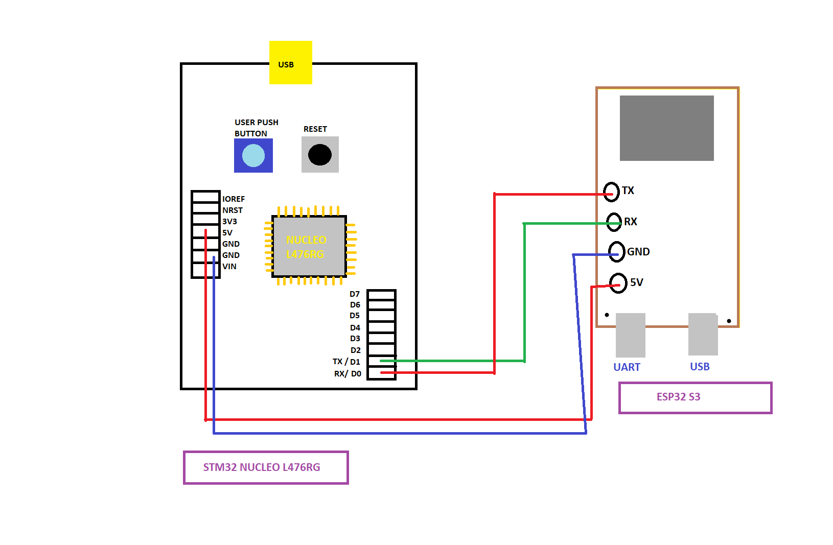
I couldn't make a detailed circuit diagram,sorry for the inconvinience,
Here's a simplified version I made.
- Mark as New
- Bookmark
- Subscribe
- Mute
- Subscribe to RSS Feed
- Permalink
- Email to a Friend
- Report Inappropriate Content
2024-01-19 1:06 AM - edited 2024-01-19 1:10 AM
Hi,
Just what i see here and what I would do :
on stm32 side :
- the send string always should have an "end mark" : (\n) -> char data_to_send[] = "Hello, PC! \n ";
- dont wait forever ... (HAL_MAX_DELAY) , just some time :
HAL_UART_Transmit(&huart2, (uint8_t *)data_to_send, strlen(data_to_send), 50);
on ESP side :
- Serial.begin() -> you know for sure , on which pins this will work then ? ( i dont...)
- Serial.print("Received: "); where is this coming out ? Dont send here so much - better nothing for now, comment it out :
// Serial.print("Received: ");
+ Now look with a scope, what happens on the rx / tx lines .
- Mark as New
- Bookmark
- Subscribe
- Mute
- Subscribe to RSS Feed
- Permalink
- Email to a Friend
- Report Inappropriate Content
2024-01-19 1:40 AM
The problem is, I am setting the default UART pin (PA2 & PA3) as Tx and Rx, but the data is being sent via the USB port.
- Mark as New
- Bookmark
- Subscribe
- Mute
- Subscribe to RSS Feed
- Permalink
- Email to a Friend
- Report Inappropriate Content
2024-01-19 1:41 AM - edited 2024-01-19 1:43 AM
You seem to be making the classic mistake of trying to do everything all at once - and then wondering why nothing works.
At the moment, you don't know whether the problem is:
- Your STM32 not transmitting properly
- Your ESP32 not receiving properly from the STM32
- Your ESP32 not sending properly to the Arduino Serial Monitor.
- Any combination of some of all of the above!
Instead, the key is to take things one step at a time; eg
- Get the transmit from your ESP32 to the Arduino Serial Monitor working reliably
- Get the receive on your ESP32 working reliably from a PC terminal
- Get the transmit from your STM32 working reliably to a PC terminal
- Finally, when you have the parts working separately, connect them all together
See also:
https://community.st.com/t5/stm32cubemx-mcus/usart-configuration/m-p/629770/highlight/true#M26974
A complex system designed from scratch never works and cannot be patched up to make it work.
- Mark as New
- Bookmark
- Subscribe
- Mute
- Subscribe to RSS Feed
- Permalink
- Email to a Friend
- Report Inappropriate Content
2024-01-19 1:56 AM
Ooooo - i didnt know this. You cannot use the uart pins on the nucleo board, that are fix wired to the st-link onboard !
Use another uart (you have MANY here! ) or define some FREE pins (in the ioc edit ) to be used for rx/tx , then it will work.
- Mark as New
- Bookmark
- Subscribe
- Mute
- Subscribe to RSS Feed
- Permalink
- Email to a Friend
- Report Inappropriate Content
2024-01-19 2:05 AM
@AScha.3 wrote:You cannot use the uart pins on the nucleo board, that are fix wired to the st-link onboard !
Indeed - much like Arduinos!
It's described in the User Manual for the board - including how to break the connection, if you wish:

@AScha.3 wrote:Use another uart (you have MANY here! )
Indeed. :thumbs_up:
A complex system designed from scratch never works and cannot be patched up to make it work.
- Mark as New
- Bookmark
- Subscribe
- Mute
- Subscribe to RSS Feed
- Permalink
- Email to a Friend
- Report Inappropriate Content
2024-01-19 2:12 AM
Use this button to properly post source code:

To get that extra row of icons, press this button:

A complex system designed from scratch never works and cannot be patched up to make it work.