
Associate II
December 5, 2023
Question

Timer in one pulse mode

  • December 5, 2023
  • 6 replies
  • 9763 views

Hi

I have a trigger ( the pink trace) who triggers one delay of 200µs with the help of the timer 3 ( a channel toggles each event, the red trace) . A IT is also generated . Another channel of this timer 3 is used to trigger a one pulse mode pwm with a 100µs period and a duty cycle of 50%. This is the green trace. But I would like to have this result for each pulse of the trigger signal( pink trace) . And it' do not !!
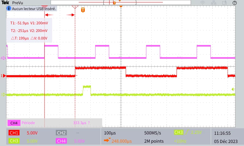
 

TEK00007.PNG

How can I rearm this PWM?  The file is  attached

Thanks for your help !

This topic has been closed for replies.

6 replies

ST Employee
December 5, 2023

Hello @MichelM38

To make sure I understood your request, you want the TIM3 that's used in one pulse mode to be triggered at every rising edge of the trigger signal?


To give better visibility on the answered topics, please click on Accept as Solution on the reply which solved your issue or answered your question.
MichelM38Author
Associate II
December 5, 2023

The tmr3 will trigger the tmr4 in one pulse mode. the tmr3 is used to delay the PWM and another signal. The tmr2 is used as an input capture ( later it will be used to determine the periode), the tmr3 is used to delay the PWM and another signal .


So the tmr2 on which the trigger signal is applied will launch the tmr3 which generate a delay of 80µs. At the end of this delay, tmr4 will be triggered for a pwm pulse in one pulse mode. the tmr3 is used to delay the PWM and another signal .

Tinnagit
Senior II
December 5, 2023

You should reset counter in input capture callback too.

__HAL_TIM_SET_COUNTER(htim, 0);
Like this

MichelM38Author
Associate II
December 5, 2023

It's already done, for the tmr3 and tmr4. And the result is not ok..

void HAL_TIM_IC_CaptureCallback(TIM_HandleTypeDef *htim)

{

if (htim == &htim2)

{

__HAL_TIM_SET_COUNTER(&htim3, 0);

HAL_TIM_OC_Start(&htim3, TIM_CHANNEL_2);

HAL_TIM_OC_Start(&htim3, TIM_CHANNEL_1);

__HAL_TIM_SET_COUNTER(&htim4, 0);

HAL_TIM_OnePulse_Start(&htim4, TIM_CHANNEL_1);

}

}


Tinnagit
Senior II
December 5, 2023

time 2 won't use after first trigger?

it's require reset counter too.


TDK
December 5, 2023

I looks like HAL_TIM_OnePulse_Start is missing the call to actually start the timer. Probably is a reason but I don't know what it is. I suspect the HAL channel state may also be busy. Try stopping the pulse before starting it.

HAL_TIM_OnePulse_Stop(&htim4, TIM_CHANNEL_1);

HAL_TIM_OnePulse_Start(&htim4, TIM_CHANNEL_1);

__HAL_TIM_ENABLE(&htim4);

Or just ignore the HAL state stuff and start the timer directly:

__HAL_TIM_ENABLE(&htim4);

or

SET_BIT(TIM4->CR1, TIM_CR1_CEN);


"If you feel a post has answered your question, please click ""Accept as Solution""."
MichelM38Author
Associate II
December 5, 2023

Hi TDK,

I tried your suggestion. Now the pwm pulses with each trigger pulse. But it seems that it is the trigger signal applied to the input capture of tmr2 that starts the pwm, not the output capture of tmr3 whereas the trigger of pwm(tmr4) is normally the output comparison of tmr3.

TEK00008.PNG

TDK
December 5, 2023

Not sure I follow what you want to achieve. Perhaps clearly draw what signals you're trying to get and indicate what's different.

"If you feel a post has answered your question, please click ""Accept as Solution""."
waclawek.jan
Super User
December 5, 2023

Also, if you can't accomplish what you want by clicking in CubeMX, it's better to avoid Cube/HAL entirely and program at register level.

JW