Turn on suggestions
Auto-suggest helps you quickly narrow down your search results by suggesting possible matches as you type.
Showing results for
- STMicroelectronics Community
- STM32 MCUs
- STM32 MCUs Products
- Re: Strange SPI Clock Form
Options
- Subscribe to RSS Feed
- Mark Topic as New
- Mark Topic as Read
- Float this Topic for Current User
- Bookmark
- Subscribe
- Mute
- Printer Friendly Page
Strange SPI Clock Form
Options
- Mark as New
- Bookmark
- Subscribe
- Mute
- Subscribe to RSS Feed
- Permalink
- Email to a Friend
- Report Inappropriate Content
2022-07-12 01:16 AM
Hi all
I have a question regarding the clock output from STM32F446VCT6 MCU.
Can anyone tell me whether the clock signal looks good for you?
Because for me it looks awful.
The signals are measured directly on MCU pin (trace is 2 cm and is not connected to anything).
The oscilloscope probe with ground spring is used.
I expected to see a square signal - but this looks somehow strange.
I run 180 MHz MCU clock and 22.5 SPI clock.
Similar signals is measured on clocks for SPI1 (PA5) and SPI4(PE12) - different pins, different traces.
I tried to use different settings for pin speed - low, medium and very high.
All other periphery is disabled (not used). Only SPI is running.
The code is generated by STM32CubeIDE.
Labels:
- Labels:
-
SPI
-
STM32F4 Series
14 REPLIES 14
Options
- Mark as New
- Bookmark
- Subscribe
- Mute
- Subscribe to RSS Feed
- Permalink
- Email to a Friend
- Report Inappropriate Content
2022-07-12 02:15 AM
What is the bandwidth of your oscilloscope and probe? For a 25MHz rectangular signal, you would need a bandwidth of at least 250MHz, otherwise the signal will be displayed incorrectly.
Options
- Mark as New
- Bookmark
- Subscribe
- Mute
- Subscribe to RSS Feed
- Permalink
- Email to a Friend
- Report Inappropriate Content
2022-07-12 02:17 AM
The scope is 350Mhz, probe max 350Mhz.
I run 10x on probe.
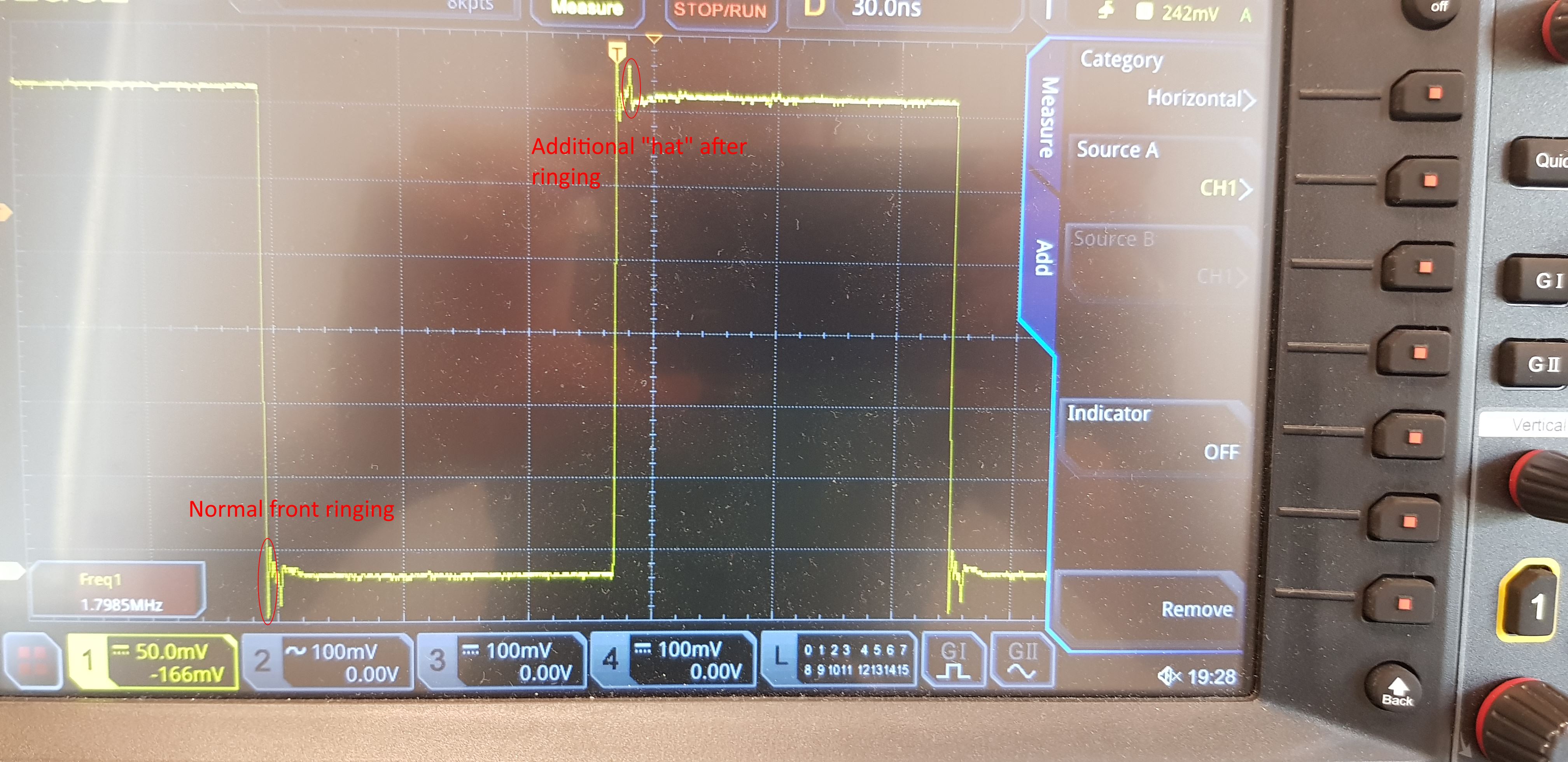
I am asking because I have some EMI noise from the CLK pin - that is why I need to understand the "hats" marked with red circle on the last picture.
Options
- Mark as New
- Bookmark
- Subscribe
- Mute
- Subscribe to RSS Feed
- Permalink
- Email to a Friend
- Report Inappropriate Content
2022-07-12 02:32 AM
The problem may be a bad solution to block the supply voltage of the MCU.
Options
- Mark as New
- Bookmark
- Subscribe
- Mute
- Subscribe to RSS Feed
- Permalink
- Email to a Friend
- Report Inappropriate Content
2022-07-12 02:41 AM
Options
- Mark as New
- Bookmark
- Subscribe
- Mute
- Subscribe to RSS Feed
- Permalink
- Email to a Friend
- Report Inappropriate Content
2022-07-12 02:50 AM
Try measuring the MCU power directly on the second channel (AC coupling and high sensitivity) to see if there is a coincidence of peaks on the signal and power suply..
Options
- Mark as New
- Bookmark
- Subscribe
- Mute
- Subscribe to RSS Feed
- Permalink
- Email to a Friend
- Report Inappropriate Content
2022-07-12 02:59 AM
Write a minimal program, which does nothing just sets given pin as GPIO output and toggles it with a loopdelay.
Try the same on a "known good" board such as Nucleo or Disco.
JW
Options
- Mark as New
- Bookmark
- Subscribe
- Mute
- Subscribe to RSS Feed
- Permalink
- Email to a Friend
- Report Inappropriate Content
2022-07-12 04:21 AM
I tried with the GPIO output - similar picture. Cannot run it faster than 1.8MHz using GPIO.
See the picture. Apart from just normal ringing after the front, there is an additional "hat" after.
I tried it on two different boards - I do not have a "reference" DK like nucleo or disco to hand.
Options
- Mark as New
- Bookmark
- Subscribe
- Mute
- Subscribe to RSS Feed
- Permalink
- Email to a Friend
- Report Inappropriate Content
2022-07-12 04:25 AM
Options
- Mark as New
- Bookmark
- Subscribe
- Mute
- Subscribe to RSS Feed
- Permalink
- Email to a Friend
- Report Inappropriate Content
2022-07-12 04:30 AM
Related Content
- STM32H7 UART TEACK forever after clock switch in STM32 MCUs Products
- cannot connect with GDB/openOCD but no problem with STM32CubeProgrammer in STM32 MCUs Products
- Losing RTC ticks after wakeup timer in STM32 MCUs Embedded software
- NUCLEO-WL33CC1 fails to connect after a succesfull programming in STM32 MCUs Wireless
- Bare Metal ADC on NUCLEO-H745ZI-Q in STM32CubeIDE (MCUs)