Turn on suggestions
Auto-suggest helps you quickly narrow down your search results by suggesting possible matches as you type.
Showing results for
- STMicroelectronics Community
- STM32 MCUs
- STM32 MCUs Products
- Re: How to reset STM32H7 timer/counter and how to ...
Options
- Subscribe to RSS Feed
- Mark Topic as New
- Mark Topic as Read
- Float this Topic for Current User
- Bookmark
- Subscribe
- Mute
- Printer Friendly Page
How to reset STM32H7 timer/counter and how to set the encoder mode?
Options
- Mark as New
- Bookmark
- Subscribe
- Mute
- Subscribe to RSS Feed
- Permalink
- Email to a Friend
- Report Inappropriate Content
2021-07-24 11:34 AM
Hi,
I am new with the STM32H7 timer/counter. I found the LPTIM_PulseCounter example which was good starting point. But I have a couple of questions:
- How can a reset the counter manually (not via automatic reload) of LPTIMER1? I could not find any HAL_LPTIM_CounterClear(), HAL_LPTIM_Counter_Reset(), HAL_LPTIM_Counter_Write(0x0000) function in HAL LPTIM Generic Driver.
- As far as I think the LPTIMER1 is capable to count quadrature encoded signals. It has two inputs, I can set the ENCODER mode and I can start the encoder mode with HAL_LPTIM_Encoder_Start (LPTIM_HandleTypeDef * hlptim, uint32_t Period) function. But I guess the period parameter should be set to 0xFFFF in order not to allow autoreload function after PERIOD count.
- Does ENCODER mode work with 32-bit timers? No need to be LPTIMER.
- I have STM32H747I-DISCO board. The input1 of the LPTIMER1 is in the Arduino connector PD12 (pin 10 of CN5). Is the Input2 of LPTIMER1 in the same CN5 connector but the next pin: pin 9 of CN5 (PD13)?
- Is there any example how to use LPTIMER1 as an encoder in STM32H747I-DISCO board?
Thanks for your help!
Louis
Solved! Go to Solution.
Labels:
- Labels:
-
LPTIM
-
STM32H7 Series
-
TIM
1 ACCEPTED SOLUTION
Accepted Solutions
Options
- Mark as New
- Bookmark
- Subscribe
- Mute
- Subscribe to RSS Feed
- Permalink
- Email to a Friend
- Report Inappropriate Content
2021-07-28 6:49 AM
It doesn't look like HAL_TIM_Encoder_Start_IT actually enable the update interrupt. You can do this manually after starting the encoder:
/* Enable the TIM Update interrupt */
__HAL_TIM_ENABLE_IT(&htim4, TIM_IT_UPDATE);
HAL_TIM_Encoder_Start_IT does enable the CC1 and CC2 interrupts, which are going to cause HAL_TIM_IC_CaptureCallback to get called. It looks like this is the way HAL intends you to use the encoder in timer mode. Set CCR1 to 0 and CCR2 to half-range to be able to detect overflows. Check for htim->Channel == HAL_TIM_ACTIVE_CHANNEL_1 or HAL_TIM_ACTIVE_CHANNEL_2 to see which is getting called.
If you feel a post has answered your question, please click "Accept as Solution".
20 REPLIES 20
Options
- Mark as New
- Bookmark
- Subscribe
- Mute
- Subscribe to RSS Feed
- Permalink
- Email to a Friend
- Report Inappropriate Content
2021-07-24 11:53 AM
> How can a reset the counter manually (not via automatic reload) of LPTIMER1? I could not find any HAL_LPTIM_CounterClear(), HAL_LPTIM_Counter_Reset(), HAL_LPTIM_Counter_Write(0x0000) function in HAL LPTIM Generic Driver.
You can write directly to the CNT register to set it to 0, but it won't reset the prescaler. To reset the counter including the prescaler, generate an update event with the EGR register, which will also reset the CNT value.
> As far as I think the LPTIMER1 is capable to count quadrature encoded signals. It has two inputs, I can set the ENCODER mode and I can start the encoder mode with HAL_LPTIM_Encoder_Start (LPTIM_HandleTypeDef * hlptim, uint32_t Period) function. But I guess the period parameter should be set to 0xFFFF in order not to allow autoreload function after PERIOD count.
Setting period to 0xFFFF is fine, and IMO the right thing to do. It still rolls over when it reaches the max value.
> Does ENCODER mode work with 32-bit timers? No need to be LPTIMER.
Yes
> I have STM32H747I-DISCO board. The input1 of the LPTIMER1 is in the Arduino connector PD12 (pin 10 of CN5). Is the Input2 of LPTIMER1 in the same CN5 connector but the next pin: pin 9 of CN5 (PD13)?
Not sure, but the answer will be in the user manual. Be aware of solder bridges sometimes needing to be closed/opened to expose or free up pins.
>Is there any example how to use LPTIMER1 as an encoder in STM32H747I-DISCO board?
Doesn't look like it. Only one example and it's on the H743-EVAL. However, the code is going to be similar on your board.
https://github.com/STMicroelectronics/STM32CubeH7/search?q=HAL_LPTIM_Encoder_Start
If you feel a post has answered your question, please click "Accept as Solution".
Options
- Mark as New
- Bookmark
- Subscribe
- Mute
- Subscribe to RSS Feed
- Permalink
- Email to a Friend
- Report Inappropriate Content
2021-07-24 11:44 PM
Hi TDK,
Thanks for the very quick reply. I can't create quadrature modulated signal at home but I will test the suggested (https://github.com/STMicroelectronics/STM32CubeH7/blob/ccb11556044540590ca6e45056e6b65cdca2deb2/Projects/STM32H743I-EVAL/Examples/LPTIM/LPTIM_Encoder/Src/main.c) sample project on Monday morning. It seems to be very close to STM320H7474I-DISCO board. Thank you for your help!!!
Best regards,
Louis
Options
- Mark as New
- Bookmark
- Subscribe
- Mute
- Subscribe to RSS Feed
- Permalink
- Email to a Friend
- Report Inappropriate Content
2021-07-26 5:15 AM
Hi TDK,
Thanks for the suggestions. The STM32H743I-EVAL (Single core version of STM32H7474I) LPTIM_Encoder example project was the closest example to me (how to configure Encoder Timer/Counter). The exmaple used LPTIM1 for encoder but I had problems with accessing to the defined INPUT1 and INPUT2 pins of LPTIMER1 in 747I-DISCO board. In the example the LPTIM1_IN1 = PD12, and LPTIM_IN2 = PE1 port pin. In STM32H747I-DISCO board the PD12 pin can be found in the STMOD+ pin7, which is accessible from the little “fanout�? board. The LPTIM1_IN2 = PE1, but I could not find PE1 nether in ARDUINO not in the STMOD+ fanout board. So, this example cannot be directly used.
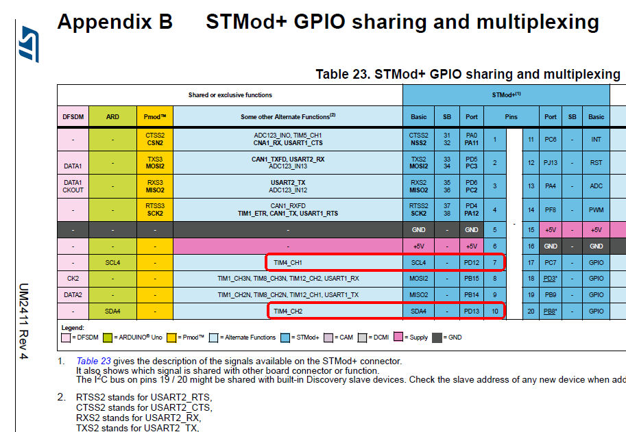
However I found (in the STM32H747I-DISCO user manual) that the STMod+ fanout connector has PD12 and PD13, which is the INPUT1 and INPUT2 of TIMER4. The TIMER4 is 32-bit counter and does support Encoder. Great, I just need to use TIMER4 instead of LPTIMER1. It seemed not to difficult job. (See attached file)
Now the problem is if a use STM32CubeMX with a new project for STM32H747I-DISCO board and if I enable TIM4 (for CM7 core) then it specifies different pins for TIMER4 in Encoder Mode, other than the STM32H747I-DISCO user manual… For TIM4 IN1 CubeMX specifies PB7 (instead of PD12) and IN2 = PD12 (Instead of PD13). I feel disturbance in the Force. Which is right?
Thank you for your help.
Best regards,
Louis
Options
- Mark as New
- Bookmark
- Subscribe
- Mute
- Subscribe to RSS Feed
- Permalink
- Email to a Friend
- Report Inappropriate Content
2021-07-26 6:51 AM
> For TIM4 IN1 CubeMX specifies PB7 (instead of PD12) and IN2 = PD12 (Instead of PD13). I feel disturbance in the Force. Which is right?
TIM4_CH2 is an option for both PB7 and PD13. If you want to change it to a different pin, click on the pin and select TIM4_CH2.
If you feel a post has answered your question, please click "Accept as Solution".
Options
- Mark as New
- Bookmark
- Subscribe
- Mute
- Subscribe to RSS Feed
- Permalink
- Email to a Friend
- Report Inappropriate Content
2021-07-26 10:52 AM
Hi TDK!
Thanks, nice idea and even it works!
However, there should be a cross reference table which shows the PIN numbers and its function(s)/alternate functions. And reverse: a cross table which shows (for example) TIMER4_CH1 can be assigned to the following GPIO pins. Do you know where can I find these tables? I could not find in the STM327H7xx manual.
Many thanks for your help
Louis
Options
- Mark as New
- Bookmark
- Subscribe
- Mute
- Subscribe to RSS Feed
- Permalink
- Email to a Friend
- Report Inappropriate Content
2021-07-26 11:02 AM
The datasheet will have that info.
If you feel a post has answered your question, please click "Accept as Solution".
Options
- Mark as New
- Bookmark
- Subscribe
- Mute
- Subscribe to RSS Feed
- Permalink
- Email to a Friend
- Report Inappropriate Content
2021-07-26 11:19 AM
Thanks TDK, I should have known. I will test the TIMER4 based encoder in STM7474I-DISCO board tomorrow.
Louis
Options
- Mark as New
- Bookmark
- Subscribe
- Mute
- Subscribe to RSS Feed
- Permalink
- Email to a Friend
- Report Inappropriate Content
2021-07-27 12:50 AM
Hi TDK,
I do hope you can answer how in the hell I can read the counted pulses form TIMER4? There is no HAL_TIM_Encoder_Read(Counter) function. The example you found just reads the count direction flags and blink LED1/3 to inform the user whether the encoder counts up or down. The closest function I found are:
/* Initialize all configured peripherals */
	MX_GPIO_Init();
	MX_TIM4_Init();

	//+++++
	// 20210727 Start encoder TIMER4. But which channel?
	//	TIM_CHANNEL_1, TIM_CHANNEL_2, TIM_CHANNEL_ALL
	//-----
	if(HAL_OK != HAL_TIM_Encoder_Start(&htim4, TIM_CHANNEL_ALL))
	{
		Error_Handler();
	}

	uint32_t encoderPulses = 0;
	uint32_t encoderPulsesAll = 0;
	uint32_t encoderPulses1 = 0;
	uint32_t encoderPulses2 = 0;
	while (1)
	{
		HAL_Delay(50);
		//+++++
		// TFS20210727	Read counter of TIMER4
		//-----
		encoderPulses = __HAL_TIM_GetCounter(&htim4);

		encoderPulses1 = HAL_TIM_ReadCapturedValue(&htim4, TIM_CHANNEL_1);
		encoderPulses2 = HAL_TIM_ReadCapturedValue(&htim4, TIM_CHANNEL_2);

		encoderPulsesAll = HAL_TIM_ReadCapturedValue(&htim4, TIM_CHANNEL_ALL);
	}
All of those returns 0 even I see the Encoder pulses on my scope. Maybe I start encoder with the wrong channel TIM_CHANNEL_ALL? Where can I found a description how I can use the Encoder mode? The "STM32H7-GPTIM" application notes is a nice document but it does not explain the usage of the Encoder. (Init, Start, Stop, Read counted pulses). I wonder how others could use encoder?
Thanks for your help.
Louis
Options
- Mark as New
- Bookmark
- Subscribe
- Mute
- Subscribe to RSS Feed
- Permalink
- Email to a Friend
- Report Inappropriate Content
2021-07-27 7:32 AM
The encoder value is stored in CNT, which can be read by __HAL_TIM_GET_COUNTER(&htim4), or directly with TIM4->CNT.
The details of how to use the encoder at a register level will be in the reference manual, if that's what you're looking for.
For HAL, just enable clock, call HAL_TIM_Encoder_Init, then call HAL_TIM_Encoder_Start.
If you feel a post has answered your question, please click "Accept as Solution".
Related Content
- Reading actual TIM repetition count after manually stopping counter in STM32 MCUs Products
- STM32F7xx: AXI Interface delays interupt service routine in STM32 MCUs Products
- STM32H7 JPEG encoding with DMA leaves empty space in STM32 MCUs Embedded software
- STM32H7 I/O Compensation cell code encoding in STM32 MCUs Embedded software
- STM32H7 JPEG Encoding does not work with DMA in STM32 MCUs TouchGFX and GUI