Problems controlling motor at low speeds and in the negative direction
- Mark as New
- Bookmark
- Subscribe
- Mute
- Subscribe to RSS Feed
- Permalink
- Email to a Friend
- Report Inappropriate Content
2022-01-28 7:20 AM
Hello,
I am starting to develop an application using the Nucleo F303RE and the IHM08M1 with the Motor Control Workbench.
My motor is driven with 24V and has a maximum current of 3.25A and a rated speed of 3590 RPM, from its datasheet I know that it has a 0.53 Ohm phase resistance, 0.43mH inductance, 4 poles but unfortunately the voltage constant is not listed (only the torque constant of 0.35 Nm/kRPM)
I configured my project to use the 3 shunt architecture, FOC and hall sensors, I modify the IHM08M1 board accordingly (removed R181, C3, C5, C7, changed the solder bridges to 3 Sh, connected both contacts from the JP1 and JP2 and kept JP9 open),
The motor profiler never worked for me, I changed the current, the max speed, but I could never make the motor turn and received after a while the message that "it is taking too long".
I configure my Motor Control Workbench as best as I could (with the motor information that I had at hand) and after playing around with the order of the motor phases and the order of the hall sensor, I could finally achieve rotation using the "Monitor" or the "Motor Pilot"
But after trying a couple of day, I haven been able to solve the following problems:
1) The motor turns smoothly from around 500 RPM up until 3950 RPM, but below 500 RPM it stutters and I receive the error "Over current"
2) Changing the direction of rotation works only some times, I have to "jump" from around 500 RPM to -500 RPM otherwise, the motor stops with an "Over current" error when trying to do low speeds or zero crossing.
3) If I stop the motor and set the starting speed anywhere from 500 to 3950 RPM it will start turning most of the times, however if I set the starting speed from -500 to -3950 RPM it will never start, it will only flick and stop with an "over current" error
I would appreciate some pointer on how to solve this problems, if more information is required I will gladly provide it.
Best regards
- Labels:
-
STM32 Motor Control
-
STM32F3 Series
- Mark as New
- Bookmark
- Subscribe
- Mute
- Subscribe to RSS Feed
- Permalink
- Email to a Friend
- Report Inappropriate Content
2022-02-04 10:34 AM
Hello @Community member
> The motor profiler never worked for me, I changed the current, the max speed, but I could never make the motor turn and received after a while the message that "it is taking too long".
The IHM08 is a little bit oversized for your motor and the accuracy of the small current read by the shunt may not be good enough. After reading your post, we tried to reproduce your issue with a motor in the same range of voltage and power as yours. Shinano LA052
We succeed to profile it after several trials with a Max Speed set at 2500rpm (instead of 4000rpm by default) and a Max current Apk=1A.
> I configure my Motor Control Workbench as best as I could (with the motor information that I had at hand) and after playing around with the order of the motor phases and the order of the hall sensor, I could finally achieve rotation using the "Monitor" or the "Motor Pilot"
What is the version of your SDK ? the version 5.Y introduces a new powerful communication protocol but requires the Pilot. The monitor targets the legacy 5.4 series.
I have faced issues similar to the one you described, and discovered it was due to an hardware issue of the hall sensors.
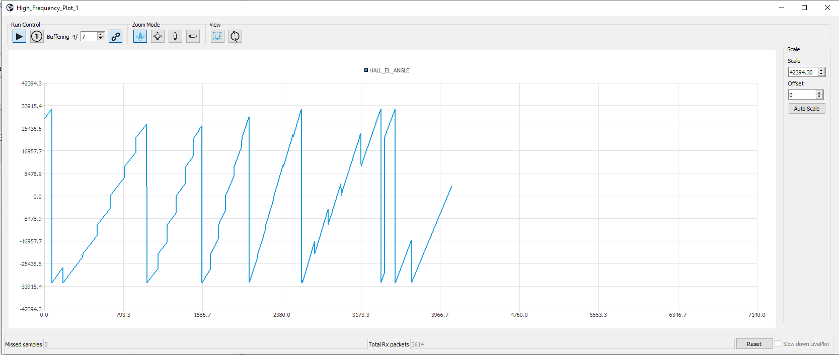
If it is the case, the MTPA option you will find in the Hall sensor configuration panel will make thing worse. Indeed, with HALL-MTPA enables, the firmware will not try to smooth the difference between the information from the hall sensors with the one computed by integrating the speed, it will take the information form the sensors without filtering. It means that if this information is not correct, you will observe something similar to the picture attached. (taken with the 5.Y.4 and the Pilot)
Could you check at the oscilloscope the quality of the pulses of your 3 hall signals ?
Regards
Cedric
- Mark as New
- Bookmark
- Subscribe
- Mute
- Subscribe to RSS Feed
- Permalink
- Email to a Friend
- Report Inappropriate Content
2022-02-10 3:01 AM
Hello @cedric H , thanks a lot for your answer.
I tried several version of your software ( 5.4.5, 5.4.8, 5.Y.4) , I indeed like the feel from the 5.Y.4, however, this project is meant to be a dual motor solution and I understand, this is still not available in that version, I such I reverted to the v5.4.8 where I have been conducting my experiments and trying to get my motors to work reliably.
Unfortunately I was not able to profile my motor even with your recommendations

With a lot of trial an error I have been able to run my motor in both directions, however, it still fails to start once or twice for every ten attempts in the negative direction, in the positive direction is a very seldom occurrence.
I changed the "placement electrical angle" in the Hall sensor configuration from 120° to 190° and tested if the motor was starting in the CW and CCW directions, at 155° I obtained the best results that I mentioned earlier, I can slow the motor down to 160-170 RPM in both directions, below that the motor stops.

The signal from my Hall Sensors looks ok, there is noise present but it doen't look very dramatic, since yesterday, I'm able to use the DAC output to debug, here a screenshot of the three hall sensor (Yellow - H1, Cyan - H2, Magenta - H3, Blue - Measured electrical angle).

As you mention at the beginning of your post, the measured currents (Ia, Ib ... ) are quite small, hence it may be difficult to improve the motor performance, reduce the rotation speed. what do you think ?
Ia@4000RPM

Iq@4000RPM

- Mark as New
- Bookmark
- Subscribe
- Mute
- Subscribe to RSS Feed
- Permalink
- Email to a Friend
- Report Inappropriate Content
2022-02-14 7:30 AM
Checking the "use MTPA" option on the "Main sensor" tab, this is how my plot looks like, I got also a current probe and this is how my current look on the Phase_U


- Mark as New
- Bookmark
- Subscribe
- Mute
- Subscribe to RSS Feed
- Permalink
- Email to a Friend
- Report Inappropriate Content
2022-08-26 4:20 PM
I'm having the same issues, how did you figure out the placement electrical angle for the hall sensors?