Turn on suggestions
Auto-suggest helps you quickly narrow down your search results by suggesting possible matches as you type.
Showing results for
- STMicroelectronics Community
- STM32 MCUs
- STM32 MCUs Products
- Re: Why is there corrupt data when sending as SPI ...
Options
- Subscribe to RSS Feed
- Mark Topic as New
- Mark Topic as Read
- Float this Topic for Current User
- Bookmark
- Subscribe
- Mute
- Printer Friendly Page
Why is there corrupt data when sending as SPI Slave?
Options
- Mark as New
- Bookmark
- Subscribe
- Mute
- Subscribe to RSS Feed
- Permalink
- Email to a Friend
- Report Inappropriate Content
2021-11-29 11:36 AM
Hello!
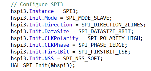
I have been trying to configure the STM32F407VE as a SPI slave. My first time configuring a SPI device ever so its all new to me. You can see my SPI settings and code as an attachment.
I am using software SS as I only have one slave and one master. Though I am polling the SS line of the master device to make sure I sync up okay as I best as I can before I only react on the master's clock signals later.
The master device is a playstation 2 running a playstation 1 game. So far what I observe on my logic analyzer matches online docs which is reassuring. Here are the docs I am referring to.
https://gamesx.com/controldata/psxcont/psxcont.htm
https://store.curiousinventor.com/guides/PS2
Where I am so far is that I am able to receive a byte from the master and am able to take some action on it. For my example, I can issue an acknowledge to the master to say I got the data okay. From what I understand, this is not part of SPI but is required when talking to a playstation 2 or 1 before it sends another byte. I have confirmed that to be true when I sent the acknowledge after the first byte exchange.
Now whenever I grabbed a byte from the master, I send a dummy byte of 0xFF to the master (full duplex). When i try to send any other value as the dummy byte, the MCU sends completely random values. There is no rhyme or reason I could find in the few hours of debugging.
I believe it has to be something wrong on how I send the byte but I think the order of actions I have makes sense as far as I concluded from reading the reference manual. Then again I am new to SPI congfiuratoin so I think there still might be an error
Has anyone else have had this strange behavior when trying to use the STM32 as a SPI slave? There are not too many examples on the internet I could find on how to do this. Those that try seem to never get it working quite right and seem to abandon the idea. There was one website I found that used one STM32 master and STM32 slave. It looked easy enough to do with the HAL but I came across similar issues so it didn't work for me.
Any hints or troubleshooting starting points is appreciated. Thank you for your time in reading my post!
Other Notes:
1) I am using the STM32CubeIDE.
2) I am using HAL for configuration.
3) Last task I had was using UARTs (and lots of I/O) and everything worked okay so I think my hardware is okay.
4) It is a custom PCB I made for my own STM32 development and learning.
5) To see data line routing on my PCB, it is attached but I think it looks okay.
6) Clock tree is attached.
Solved! Go to Solution.
Labels:
- Labels:
-
SPI
-
STM32F4 Series
-
UART-USART
1 ACCEPTED SOLUTION
Accepted Solutions
Options
- Mark as New
- Bookmark
- Subscribe
- Mute
- Subscribe to RSS Feed
- Permalink
- Email to a Friend
- Report Inappropriate Content
2021-11-29 10:06 PM
I think I found the issue, I had the wrong setting! I am going to play around with some more to make sure but the data looks better now.
7 REPLIES 7
Options
- Mark as New
- Bookmark
- Subscribe
- Mute
- Subscribe to RSS Feed
- Permalink
- Email to a Friend
- Report Inappropriate Content
2021-11-29 8:23 PM
I would suggest to have the NSS gpio signal as exti interrupt, so you know when an exchange occured and you should read, process and prepare the response out. Now in slave mode, you don't control the clock tempo and must be ready to communicate asap. Typically a DMA with a spi TX and RX channels will point to buffers. Next is to decide buffer rollover / cyclic or block length limited with critical latency. If your SPI do support FIFO with DMA cyclic mode, some sw workaround maybe needed. And remember that as you are receiving data, you and sending what you have already prepared, which is different than usart.
Options
- Mark as New
- Bookmark
- Subscribe
- Mute
- Subscribe to RSS Feed
- Permalink
- Email to a Friend
- Report Inappropriate Content
2021-11-29 8:25 PM
Thanks for the answer! I am not well versed in interrupts or DMA so I went with polling the CS line. I do react fast enough to it I just don't understand why the data is random when I throw some data into the TX buffer.
Options
- Mark as New
- Bookmark
- Subscribe
- Mute
- Subscribe to RSS Feed
- Permalink
- Email to a Friend
- Report Inappropriate Content
2021-11-29 8:33 PM
Options
- Mark as New
- Bookmark
- Subscribe
- Mute
- Subscribe to RSS Feed
- Permalink
- Email to a Friend
- Report Inappropriate Content
2021-11-29 9:54 PM
As an update I tried placing a 0.1uF cap on the clock line because it appeared maybe less than ideal. Though it was so much capacitance that it made it appear like DC. My IC may be damaged but it seems to function okay with everything else. I can always try to use a black pill and see if I get the same problem.
Options
- Mark as New
- Bookmark
- Subscribe
- Mute
- Subscribe to RSS Feed
- Permalink
- Email to a Friend
- Report Inappropriate Content
2021-11-29 10:06 PM
Options
- Mark as New
- Bookmark
- Subscribe
- Mute
- Subscribe to RSS Feed
- Permalink
- Email to a Friend
- Report Inappropriate Content
2021-11-30 6:58 AM
And remember that an embedded guy always start do bringup and debug with oscilloscope first.... logic analyser comes later.
Options
- Mark as New
- Bookmark
- Subscribe
- Mute
- Subscribe to RSS Feed
- Permalink
- Email to a Friend
- Report Inappropriate Content
2021-11-30 7:23 AM
I def need one of those. Do you have an affordable suggestion for one I should I get?
Related Content
- ESP32-S3 I2C Recovery: Unstuck Slave Holding SCL Low & Reinit I2C Without Reset in STM32CubeIDE (MCUs)
- I2C slave on a STM32F030T4P6 with HAL callbacks not working in STM32 MCUs Products
- STM32H753ZI UART TX DMA in STM32 MCUs Products
- PC13 GPIO Usage recommendation on STM32G491MCT in STM32 MCUs Products
- SPI as master and FPGA as slave for some bits in STM32 MCUs Products