

Question
Stm32H7 DMA ADC Low Bit Resolution
Hello Everyone,
I am using the stm32h7 to sample 4 channels from adc1 using the DMA.
I am using circular mode with half word size. I start the dma and let it fill up a memory buffer:
volatile uint16_t adcInsDMA[4*ADCBLOCKSIZE] = {0};

HAL_StatusTypeDef status = HAL_ADC_Start_DMA(&hadc1, (uint32_t*)&adcInsDMA[0], 4*ADCBLOCKSIZE);
This works, however It looks like I am only getting 6bits of resolution. and not 16.
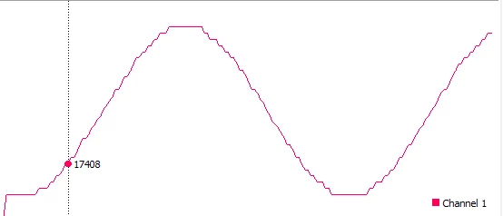
I consistently get only 63 distinct value no matter when I sample, or what the speed is of the incoming signal etc.
Here are my initialization settings generated by CUBEIDE:
/* ADC1 init function */
void MX_ADC1_Init(void)
{
 ADC_MultiModeTypeDef multimode = {0};
 ADC_ChannelConfTypeDef sConfig = {0};

 /** Common config
 */
 hadc1.Instance = ADC1;
 hadc1.Init.ClockPrescaler = ADC_CLOCK_ASYNC_DIV1;
 hadc1.Init.Resolution = ADC_RESOLUTION_16B;
 hadc1.Init.ScanConvMode = ADC_SCAN_ENABLE;
 hadc1.Init.EOCSelection = ADC_EOC_SEQ_CONV;
 hadc1.Init.LowPowerAutoWait = DISABLE;
 hadc1.Init.ContinuousConvMode = ENABLE;
 hadc1.Init.NbrOfConversion = 4;
 hadc1.Init.DiscontinuousConvMode = DISABLE;
 hadc1.Init.ExternalTrigConv = ADC_SOFTWARE_START;
 hadc1.Init.ExternalTrigConvEdge = ADC_EXTERNALTRIGCONVEDGE_NONE;
 hadc1.Init.ConversionDataManagement = ADC_CONVERSIONDATA_DMA_CIRCULAR;
 hadc1.Init.Overrun = ADC_OVR_DATA_OVERWRITTEN;
 hadc1.Init.LeftBitShift = ADC_LEFTBITSHIFT_NONE;
 hadc1.Init.OversamplingMode = DISABLE;
 if (HAL_ADC_Init(&hadc1) != HAL_OK)
 {
 Error_Handler();
 }
 /** Configure the ADC multi-mode
 */
 multimode.Mode = ADC_MODE_INDEPENDENT;
 if (HAL_ADCEx_MultiModeConfigChannel(&hadc1, &multimode) != HAL_OK)
 {
 Error_Handler();
 }
 /** Configure Regular Channel
 */
 sConfig.Channel = ADC_CHANNEL_3;
 sConfig.Rank = ADC_REGULAR_RANK_1;
 sConfig.SamplingTime = ADC_SAMPLETIME_32CYCLES_5;
 sConfig.SingleDiff = ADC_SINGLE_ENDED;
 sConfig.OffsetNumber = ADC_OFFSET_NONE;
 sConfig.Offset = 0;
 sConfig.OffsetSignedSaturation = DISABLE;
 if (HAL_ADC_ConfigChannel(&hadc1, &sConfig) != HAL_OK)
 {
 Error_Handler();
 }
 /** Configure Regular Channel
 */
 sConfig.Channel = ADC_CHANNEL_4;
 sConfig.Rank = ADC_REGULAR_RANK_2;
 if (HAL_ADC_ConfigChannel(&hadc1, &sConfig) != HAL_OK)
 {
 Error_Handler();
 }
 /** Configure Regular Channel
 */
 sConfig.Channel = ADC_CHANNEL_7;
 sConfig.Rank = ADC_REGULAR_RANK_3;
 if (HAL_ADC_ConfigChannel(&hadc1, &sConfig) != HAL_OK)
 {
 Error_Handler();
 }
 /** Configure Regular Channel
 */
 sConfig.Channel = ADC_CHANNEL_8;
 sConfig.Rank = ADC_REGULAR_RANK_4;
 if (HAL_ADC_ConfigChannel(&hadc1, &sConfig) != HAL_OK)
 {
 Error_Handler();
 }

}

void HAL_ADC_MspInit(ADC_HandleTypeDef* adcHandle)
{

 GPIO_InitTypeDef GPIO_InitStruct = {0};
 if(adcHandle->Instance==ADC1)
 {
 /* USER CODE BEGIN ADC1_MspInit 0 */

 /* USER CODE END ADC1_MspInit 0 */
 /* ADC1 clock enable */
 __HAL_RCC_ADC12_CLK_ENABLE();

 __HAL_RCC_GPIOA_CLK_ENABLE();
 __HAL_RCC_GPIOC_CLK_ENABLE();
 /**ADC1 GPIO Configuration
 PA6 ------> ADC1_INP3
 PA7 ------> ADC1_INN3
 PA7 ------> ADC1_INP7
 PC4 ------> ADC1_INP4
 PC5 ------> ADC1_INN4
 PC5 ------> ADC1_INP8
 */
 GPIO_InitStruct.Pin = IN_SIG_1_ADC_Pin|IN_SIG_2_ADC_Pin;
 GPIO_InitStruct.Mode = GPIO_MODE_ANALOG;
 GPIO_InitStruct.Pull = GPIO_NOPULL;
 HAL_GPIO_Init(GPIOA, &GPIO_InitStruct);

 GPIO_InitStruct.Pin = IN_SIG_3_ADC_Pin|IN_SIG_4_ADC_Pin;
 GPIO_InitStruct.Mode = GPIO_MODE_ANALOG;
 GPIO_InitStruct.Pull = GPIO_NOPULL;
 HAL_GPIO_Init(GPIOC, &GPIO_InitStruct);

 /* ADC1 DMA Init */
 /* ADC1 Init */
 hdma_adc1.Instance = DMA1_Stream0;
 hdma_adc1.Init.Request = DMA_REQUEST_ADC1;
 hdma_adc1.Init.Direction = DMA_PERIPH_TO_MEMORY;
 hdma_adc1.Init.PeriphInc = DMA_PINC_DISABLE;
 hdma_adc1.Init.MemInc = DMA_MINC_ENABLE;
 hdma_adc1.Init.PeriphDataAlignment = DMA_PDATAALIGN_HALFWORD;
 hdma_adc1.Init.MemDataAlignment = DMA_MDATAALIGN_HALFWORD;
 hdma_adc1.Init.Mode = DMA_CIRCULAR;
 hdma_adc1.Init.Priority = DMA_PRIORITY_LOW;
 hdma_adc1.Init.FIFOMode = DMA_FIFOMODE_ENABLE;
 hdma_adc1.Init.FIFOThreshold = DMA_FIFO_THRESHOLD_FULL;
 hdma_adc1.Init.MemBurst = DMA_MBURST_SINGLE;
 hdma_adc1.Init.PeriphBurst = DMA_PBURST_SINGLE;
 if (HAL_DMA_Init(&hdma_adc1) != HAL_OK)
 {
 Error_Handler();
 }

 __HAL_LINKDMA(adcHandle,DMA_Handle,hdma_adc1);

 /* USER CODE BEGIN ADC1_MspInit 1 */

 /* USER CODE END ADC1_MspInit 1 */
 }
}

void HAL_ADC_MspDeInit(ADC_HandleTypeDef* adcHandle)
{

 if(adcHandle->Instance==ADC1)
 {
 /* USER CODE BEGIN ADC1_MspDeInit 0 */

 /* USER CODE END ADC1_MspDeInit 0 */
 /* Peripheral clock disable */
 __HAL_RCC_ADC12_CLK_DISABLE();

 /**ADC1 GPIO Configuration
 PA6 ------> ADC1_INP3
 PA7 ------> ADC1_INN3
 PA7 ------> ADC1_INP7
 PC4 ------> ADC1_INP4
 PC5 ------> ADC1_INN4
 PC5 ------> ADC1_INP8
 */
 HAL_GPIO_DeInit(GPIOA, IN_SIG_1_ADC_Pin|IN_SIG_2_ADC_Pin);

 HAL_GPIO_DeInit(GPIOC, IN_SIG_3_ADC_Pin|IN_SIG_4_ADC_Pin);

 /* ADC1 DMA DeInit */
 HAL_DMA_DeInit(adcHandle->DMA_Handle);
 /* USER CODE BEGIN ADC1_MspDeInit 1 */

 /* USER CODE END ADC1_MspDeInit 1 */
 }
}
Any Ideas on what I could be missing would be appreaciated!
Thanks,
Trevor
