Turn on suggestions
Auto-suggest helps you quickly narrow down your search results by suggesting possible matches as you type.
Showing results for
- STMicroelectronics Community
- STM32 MCUs
- STM32 MCUs Products
- Re: RCC configuration results in HardFault (STM32F...
Options
- Subscribe to RSS Feed
- Mark Topic as New
- Mark Topic as Read
- Float this Topic for Current User
- Bookmark
- Subscribe
- Mute
- Printer Friendly Page
RCC configuration results in HardFault (STM32F411CEU6).
Options
- Mark as New
- Bookmark
- Subscribe
- Mute
- Subscribe to RSS Feed
- Permalink
- Email to a Friend
- Report Inappropriate Content
2023-05-01 04:13 PM
I have a board that is running well. There are about 50+ PCBs in production operating fine. The firmware is pretty complex, but the hardware relatively simple, just some SPI devices and some PWM outputs.
I revved the board, and the new board doesn't work at all. Well, it works enough to execute some code, but not much. So to debug, I started with a blinky program:
int main(void)
{
 HAL_Init();
 SystemClock_Config();
 MX_GPIO_Init();

 while (1)
 {
	 HAL_GPIO_TogglePin(FAULT_GPIO_Port, FAULT_Pin);
	 HAL_Delay(1000);
 }
}
If I configure the RCC to use the HSI, the program gets as far as `HAL_Delay(1000)` at which point it chokes on `HAL_GetTick()`.
If I configure the RCC to use the HSE (a crystal is present), the program only gets as far as `SystemClock_Config()`, where it again chokes on `HAL_GetTick()` or sometimes `HAL_RCC_OscConfig()`.
By "choke" I mean it throws a HardFault. Though for a reason I can't understand, it won't execute my handler.
So, the code runs ok using the HSI at 16MHz until the RCC is configured. Then, whether configured to use the HSI/PLL or HSE/PLL, it continues to execute until the first HAL_Delay().
I don't think there is anything about `HAL_Delay` specifically, since all it does is return a `volatlile int`; but rather execution becomes unstable once RCC is configured.
So, what could be causing RCC to freak out?
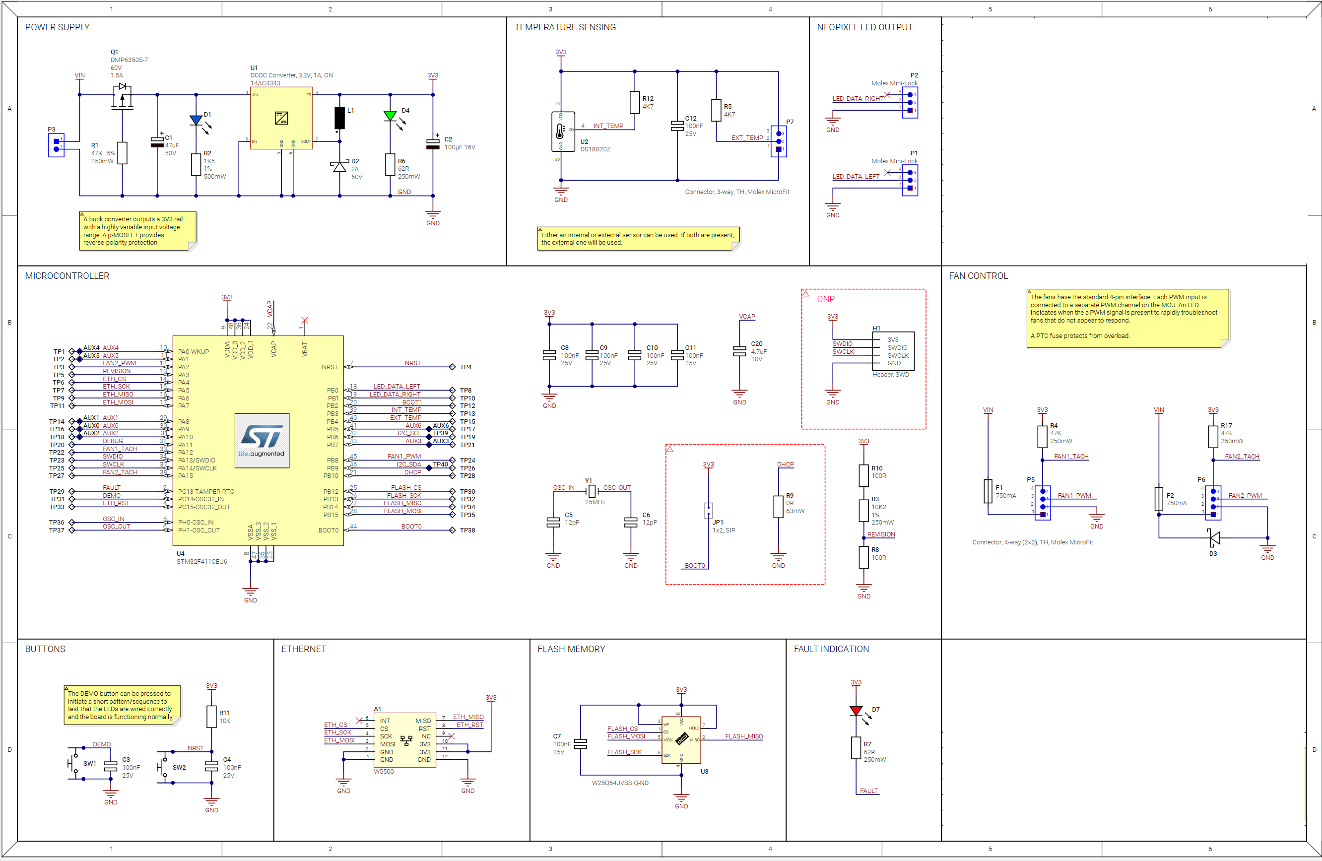
Power supply is a smooth 3.300V and there are 4 100nF bypass caps, one per Vdd/Vss pair, and Vcap has a 4.7uF.
The only thing I see that I missed is that BOOT0 doesn't have a pull-down.
A redacted schematic is attached.
Solved! Go to Solution.
Labels:
- Labels:
-
DEBUG
-
RCC
-
STM32F4 Series
1 ACCEPTED SOLUTION
Accepted Solutions
Options
- Mark as New
- Bookmark
- Subscribe
- Mute
- Subscribe to RSS Feed
- Permalink
- Email to a Friend
- Report Inappropriate Content
2023-05-02 08:04 AM
I'm back. As I suspected the issue was that I left BOOT0 floating. After wiring it to ground, the blinky sanity check operates normally.
With BOOT0 left to float, execution does predictably commence from flash at 0x08000000; but further execution is erratic.
3 REPLIES 3
Options
- Mark as New
- Bookmark
- Subscribe
- Mute
- Subscribe to RSS Feed
- Permalink
- Email to a Friend
- Report Inappropriate Content
2023-05-01 04:55 PM
Check PLL gearing. Is appropriate for 25 MHz HSE, and adequate wait states on flash.
Check HSE_VALUE in stm32f4xx_hal_conf.h
Tips, Buy me a coffee, or three.. PayPal Venmo
Up vote any posts that you find helpful, it shows what's working..
Up vote any posts that you find helpful, it shows what's working..
Options
- Mark as New
- Bookmark
- Subscribe
- Mute
- Subscribe to RSS Feed
- Permalink
- Email to a Friend
- Report Inappropriate Content
2023-05-02 07:47 AM
Thanks for the suggestion.
I checked the PLL configuration for sanity. I also removed PLL from the equation and ran HSI directly at 16MHz -- same issue.
So I went completely back to backs and created an empty project. The only thing I configured was a GPIO output to flash an LED on. -- It didn't work.
So, I flashed the same code to an off-the-shelf "black pill" and it worked. So I'll take another look at the PCB to see what I can come up with. I'll start with the floating BOOT0.
I'll report back in case I find anything interesting.
Options
- Mark as New
- Bookmark
- Subscribe
- Mute
- Subscribe to RSS Feed
- Permalink
- Email to a Friend
- Report Inappropriate Content
2023-05-02 08:04 AM
I'm back. As I suspected the issue was that I left BOOT0 floating. After wiring it to ground, the blinky sanity check operates normally.
With BOOT0 left to float, execution does predictably commence from flash at 0x08000000; but further execution is erratic.
Related Content
- Assistance with LAN LWIP Configuration on STM32H7S7DK Development Board (RMII) in STM32 MCUs Embedded software
- Problem with UART in secure and unprivileged mode U5 in STM32 MCUs Security
- Re: HardFault UDP Client in STM32 MCUs Embedded software
- STM32F411CEU6 via STLINK V2 - C13 (Board LED: on/off) - configuration check under Linux with stlink-gui failed in STM32 MCUs Embedded software
- STM32U5A5 Jump to Bootloader from ThreadX Application with TrustZone enabled in STM32 MCUs Embedded software