Problems with reading through SPI with DMA on STM32F407
Hi!
So I configured my SPI to work with DMA and with external CS. Before my main loop I set CS high, and everytime before I initialize communication on SPI with DMA i set CS low. Then, after communication is done I go to interrupt on that event and set CS high again (don't know if it is the best way on doing that, let me know if there is one better :) ).
Okay, so in while(1) loop I transmit-receive data from LIS3DSH. I sent 3 commands and receive 3 sets of data. The trick is that it's working really strange.
So, when I'm sending WHO_AM_I (0x8F) I should receive 0x3F, but whoami value is 0x00.
When I'm sending INFO_1 (0x8D) I should receive 0x21, but info1 value is 0x3F.
And when I'm sending INFO_2 (0x8E) I should receive 0x00, but info2 value is 0x21.
I check tx-rx on oscilloscope, and communication looks perfect, just the values of my variables are weird.
I know that using DMA on SPI causes it go on full speed, maybe I'm just too fast and my variables are changing too slow? I'm not sure.
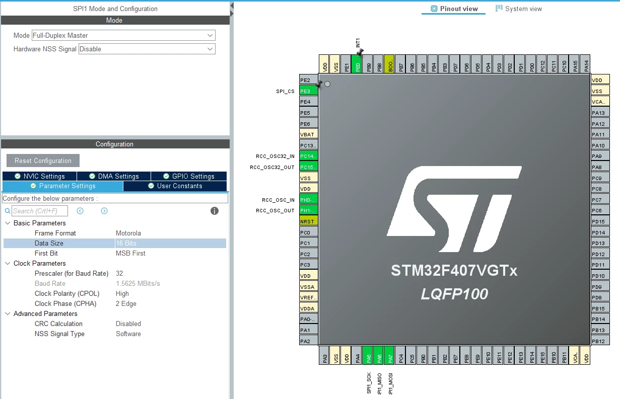
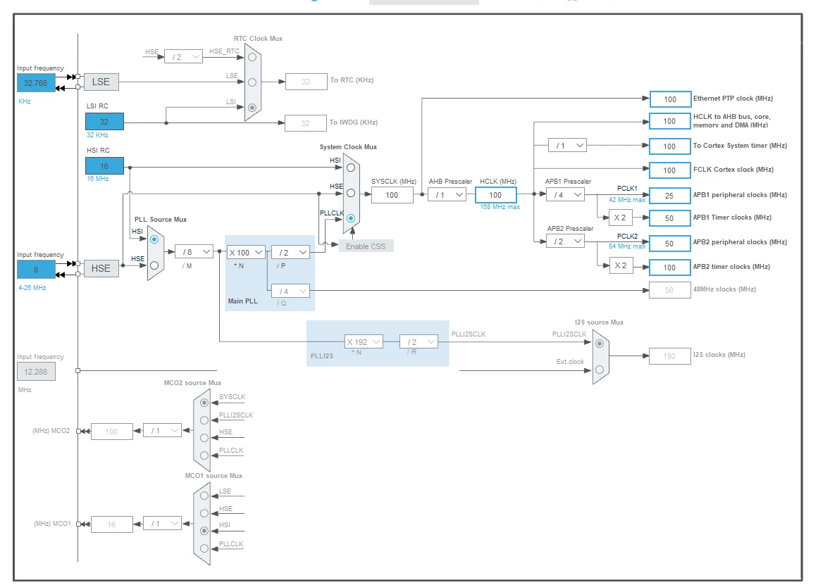
Here is my code and configuration in CubeMX.
I'm using:
- STM32F407VG
- LIS3DSH (it's not its problem, he works fine)
- Atollic TrueStudio 9.3
- CubeMX 6.2.1
uint8_t whoami, info1, info2;

int main(){
 HAL_GPIO_WritePin(SPI_CS_GPIO_Port,SPI_CS_Pin, GPIO_PIN_SET); //CS=1
 while (1)
 {
	 whoami = LIS3DSH_Read(WHO_AM_I);
	 info1 = LIS3DSH_Read(INFO1);
	 info2 = LIS3DSH_Read(INFO2);
 }
}
uint16_t LIS3DSH_Read(uint16_t address){
uint16_t rx;
HAL_GPIO_WritePin(SPI_CS_GPIO_Port,SPI_CS_Pin, GPIO_PIN_RESET); //CS=0
uint16_t tx = (0x80 | address) << 8; //RW=1
HAL_SPI_TransmitReceive_DMA(&hspi1,(uint16_t*)&tx, (uint16_t*)&rx, 1);
return rx;
}
void HAL_SPI_TxRxCpltCallback(SPI_HandleTypeDef *hspi){
HAL_GPIO_WritePin(SPI_CS_GPIO_Port,SPI_CS_Pin, GPIO_PIN_SET); //CS=1
}void HAL_SPI_MspInit(SPI_HandleTypeDef* hspi)
{
GPIO_InitTypeDef GPIO_InitStruct = {0};
if(hspi->Instance==SPI1)
{
/* USER CODE BEGIN SPI1_MspInit 0 */
/* USER CODE END SPI1_MspInit 0 */
/* Peripheral clock enable */
__HAL_RCC_SPI1_CLK_ENABLE();
__HAL_RCC_GPIOA_CLK_ENABLE();
/**SPI1 GPIO Configuration
PA5 ------> SPI1_SCK
PA6 ------> SPI1_MISO
PA7 ------> SPI1_MOSI
*/
GPIO_InitStruct.Pin = GPIO_PIN_5|GPIO_PIN_6|GPIO_PIN_7;
GPIO_InitStruct.Mode = GPIO_MODE_AF_PP;
GPIO_InitStruct.Pull = GPIO_NOPULL;
GPIO_InitStruct.Speed = GPIO_SPEED_FREQ_VERY_HIGH;
GPIO_InitStruct.Alternate = GPIO_AF5_SPI1;
HAL_GPIO_Init(GPIOA, &GPIO_InitStruct);
/* SPI1 DMA Init */
/* SPI1_RX Init */
hdma_spi1_rx.Instance = DMA2_Stream0;
hdma_spi1_rx.Init.Channel = DMA_CHANNEL_3;
hdma_spi1_rx.Init.Direction = DMA_PERIPH_TO_MEMORY;
hdma_spi1_rx.Init.PeriphInc = DMA_PINC_DISABLE;
hdma_spi1_rx.Init.MemInc = DMA_MINC_ENABLE;
hdma_spi1_rx.Init.PeriphDataAlignment = DMA_PDATAALIGN_HALFWORD;
hdma_spi1_rx.Init.MemDataAlignment = DMA_MDATAALIGN_HALFWORD;
hdma_spi1_rx.Init.Mode = DMA_NORMAL;
hdma_spi1_rx.Init.Priority = DMA_PRIORITY_LOW;
hdma_spi1_rx.Init.FIFOMode = DMA_FIFOMODE_DISABLE;
if (HAL_DMA_Init(&hdma_spi1_rx) != HAL_OK)
{
Error_Handler();
}
__HAL_LINKDMA(hspi,hdmarx,hdma_spi1_rx);
/* SPI1_TX Init */
hdma_spi1_tx.Instance = DMA2_Stream3;
hdma_spi1_tx.Init.Channel = DMA_CHANNEL_3;
hdma_spi1_tx.Init.Direction = DMA_MEMORY_TO_PERIPH;
hdma_spi1_tx.Init.PeriphInc = DMA_PINC_DISABLE;
hdma_spi1_tx.Init.MemInc = DMA_MINC_ENABLE;
hdma_spi1_tx.Init.PeriphDataAlignment = DMA_PDATAALIGN_HALFWORD;
hdma_spi1_tx.Init.MemDataAlignment = DMA_MDATAALIGN_HALFWORD;
hdma_spi1_tx.Init.Mode = DMA_NORMAL;
hdma_spi1_tx.Init.Priority = DMA_PRIORITY_LOW;
hdma_spi1_tx.Init.FIFOMode = DMA_FIFOMODE_DISABLE;
if (HAL_DMA_Init(&hdma_spi1_tx) != HAL_OK)
{
Error_Handler();
}
__HAL_LINKDMA(hspi,hdmatx,hdma_spi1_tx);
/* SPI1 interrupt Init */
HAL_NVIC_SetPriority(SPI1_IRQn, 0, 0);
HAL_NVIC_EnableIRQ(SPI1_IRQn);
/* USER CODE BEGIN SPI1_MspInit 1 */
/* USER CODE END SPI1_MspInit 1 */
}
}