Turn on suggestions
Auto-suggest helps you quickly narrow down your search results by suggesting possible matches as you type.
Showing results for
- STMicroelectronics Community
- STM32 MCUs
- STM32 MCUs Motor control
- Understanding PLL State Observer
Options
- Subscribe to RSS Feed
- Mark Topic as New
- Mark Topic as Read
- Float this Topic for Current User
- Bookmark
- Subscribe
- Mute
- Printer Friendly Page
Understanding PLL State Observer
Options
- Mark as New
- Bookmark
- Subscribe
- Mute
- Subscribe to RSS Feed
- Permalink
- Email to a Friend
- Report Inappropriate Content
2024-05-20 11:47 AM - edited 2024-05-20 12:06 PM
Hardware: EVSPIN32G4-Dual
Motors: 2x Moons BLDC R57BLB50L2, Hall-effect sensors not connected or desired.
Application - 2x BLDC on shared timing pulley (no slip) system. 1:1 pulley ratio between motors. Goal: equal load distribution between the two motors
Current Sense model: single shunt PLL for each motor
Setup:
I currently rev-up with Motor 1, and after Motor1 is running and stable, I use the second motor in torque mode, driving torque reference with feedback from the Motor 1.
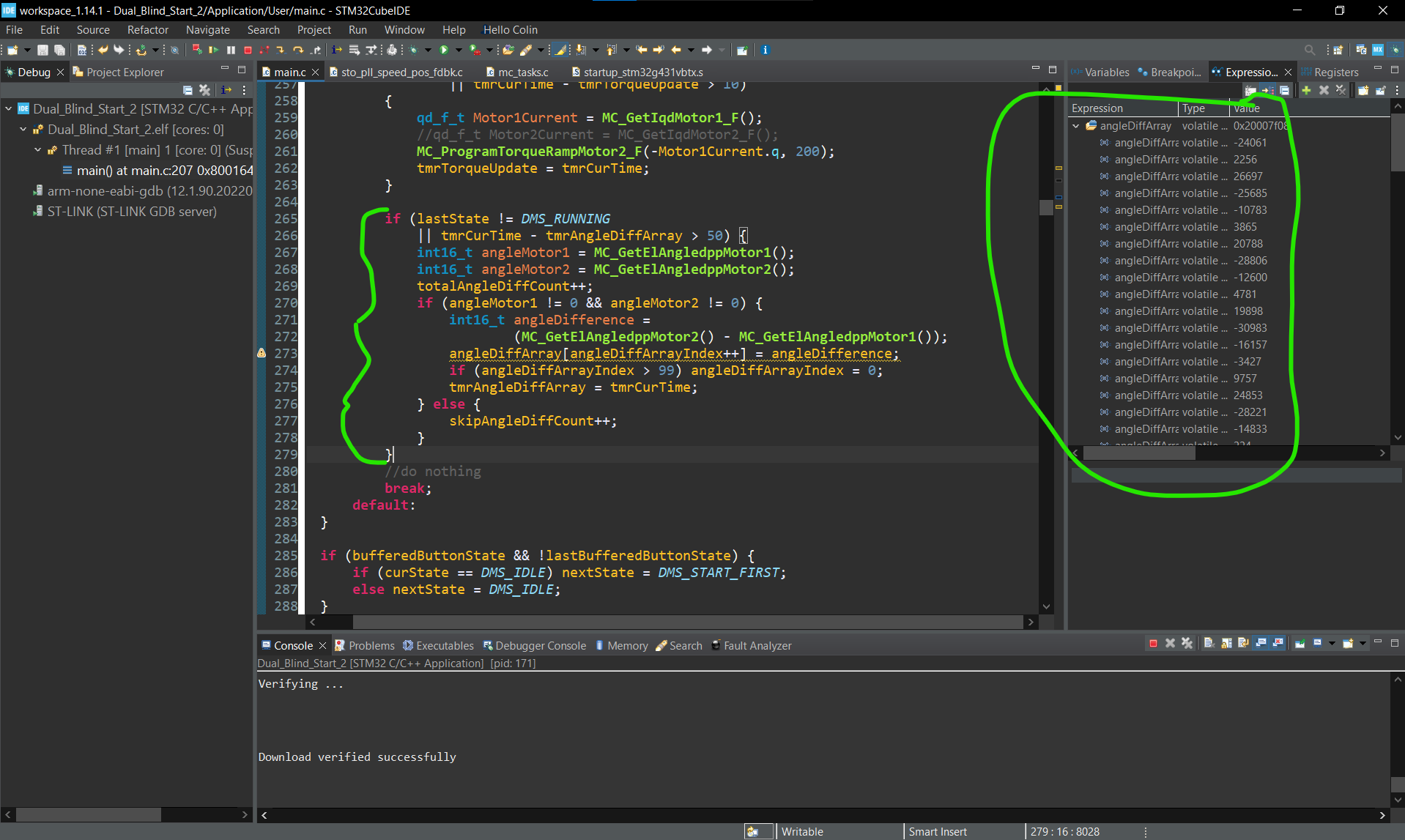
I would like to be able to perform a calibration that would read the electrical angle difference of the mounting of the two motors, then use that offset to perform a startup procedure with both motors at the same time. While both rotors are running, I read use MC_GetElAngledppMotor1() and MC_GetElAngledppMotor2(). I take a measurement every 50ms, find the difference, and store it in a buffer. For development, I am using the debugger to break the code and read from the buffer. I expect to get a consistent angle difference, as the two motors are unable to spin relative to each other, but I get wildly varying values.
I was reading in sto_pll_speed_pos_fdbk.c, and am trying to make sense of the detection algorithm reasoning. From reading about single-shunt topology, I understand that the hardware should be able to extract all three phase currents from a single shunt resistor, and these currents are used as speed/position feedback, and I assume that the rotor position and speed should be able to be inferred from that information.
What I see is that the position is not calculated directly from the momentary currents, but rather computed integral of the calculated speed. This process may cause drift and may be causing my inconsistent angle measurements.
So, here are my questions regarding your PLL state observer:
1: How do I convert from the int16 output of MC_GetElAngledppMotor2 to an angle in degrees (0-360)
2: What is the reasoning behind calculating the rotor position as the integral of the calculated speed, rather than directly. Is this a hardware limitation? If so, would other hardware give a more reliable angle measurement.
This discussion is locked. Please start a new topic to ask your question.
1 REPLY 1
Options
- Mark as New
- Bookmark
- Subscribe
- Mute
- Subscribe to RSS Feed
- Permalink
- Email to a Friend
- Report Inappropriate Content
2024-05-21 1:00 AM - edited 2024-05-21 6:38 AM
Hello ccut93,
You can find the PLL theory description in the MCSDK User Manual (Open WorkBench -> About -> Documentations -> Documentation -> in the newly open browser window click on User Manual -> Speed & position feedback sensorless algorithms)
I don't really understand what you mean by calculating angle directly. Using dpp units, the integration becomes a single addition, and this is more than enough for most use cases. Applications such as the one you are describing would benefit greatly from sensors, as I doubt you can achieve such precision using STO PLL algorithm.
Concerning the conversion from int16 to degrees, you can check the User Manual, in Measurement Units used by the firmware.
If you agree with my answer, please consider accepting it by clicking on 'Accept as solution'.
Hope this will help,
Gaël A.
Hope this will help,
Gaël A.
Related Content
- NUCLEO-H533RE USB custom DFU method in STM32 MCUs Embedded software
- Aliro Software Expansion – CryptoInit() Always Returns False in STM32 MCUs Security
- entering system bootloader on STM32U31 on empty check mechanism in STM32 MCUs Products
- generate multithread safe random generator (NX_RAND) for NetX Duo & newlib in STM32CubeMX (MCUs)
- GPIO: What Happens at the MOSFET Level When You Run Your Code? - Part 1 in STM32 MCUs Products