Turn on suggestions
Auto-suggest helps you quickly narrow down your search results by suggesting possible matches as you type.
Showing results for
- STMicroelectronics Community
- STM32 MCUs
- STM32 MCUs Motor control
- Tunning the gains of FOC loop in the ACIM implemen...
Options
- Subscribe to RSS Feed
- Mark Topic as New
- Mark Topic as Read
- Float this Topic for Current User
- Bookmark
- Subscribe
- Mute
- Printer Friendly Page
Tunning the gains of FOC loop in the ACIM implementation
Options
- Mark as New
- Bookmark
- Subscribe
- Mute
- Subscribe to RSS Feed
- Permalink
- Email to a Friend
- Report Inappropriate Content
2024-07-23 7:46 AM
Hello everyone,
I'm working on a proposal for an STM32 MC SDK AC Induction Motor using the STEVAL-IHM023V3, NUCLEO-G431RB, and NUCLEO-IHM09M1 boards in the development environment. I've encountered some challenges while setting up the project and testing.
Setting Up LSO Gains
While creating the project in MC Workbench (MC WB), I came across some variables whose values I'm unsure about, such as the KP and Ki gains for the LSO observer. The ST documentation mentions a general gain range of 1-1.5 for the observer, but it doesn't provide information about the controller bandwidth or how to manually edit KP and Ki.

Current and Speed Controller Gains
Based on my understanding of FOC loop theory, I estimated the KP and Ki values for the speed and current controllers. However, during testing with Motor Pilot, it seems the values have specific units, and I'm unsure how to adapt my values to them (see attached image).

Experimental Issues
Using some estimated values, I was able to build the project. However, in most cases, I've encountered stability issues when the current and speed Ki values are non-zero. Additionally, the observed speed doesn't match the actual speed. Furthermore, if the motor attempts to reach its nominal speed (around 1700 rpm), instability occurs upon reaching that speed, with errors like "speed feedback error" or "overcurrent error" appearing in Motor Pilot.
NOTE: I understand that some of these problems might be related to the motor's electrical parameters. However, it's important to note that these parameters weren't obtainable through the profiler because it's unavailable for these boards. I had to rely on experimental testing and estimations to obtain them.
Finally, I would greatly appreciate any information or suggestions you might have to help me troubleshoot these issues.
More details about my setup :
[VERSION]: MCSDK 6.2.1
[TOOL]: MC WB & Motor Pilot
Labels:
- Labels:
-
FOC
-
MC Workbench
-
Motor Pilot
3 REPLIES 3
Options
- Mark as New
- Bookmark
- Subscribe
- Mute
- Subscribe to RSS Feed
- Permalink
- Email to a Friend
- Report Inappropriate Content
2024-07-29 10:21 AM
Hello Carlos,
The Kp/Ki of the observer are used to compute the observed electrical angle : the integral part of a PI is used as an integrator. The PI is fed with the observed speed so we can retrieve the observed rotor angle -> d(theta)/dt = speed. These Kp/Ki (of the observer) have to be set in order to get acceptable BW and to be in line with the max electrical speed/current/.. of your system.
Starting from scratch I would recommend to use an external speed sensor that would give you the rotor speed reading. From there you can adjust the torque/flux current controller BW thanks to the torque/flux Kp+Ki together with a current probe (same Kp/Ki value for torque and flux is fine to start with)... you can check the motor current in 1 phase until the Kp/Ki provide satisfactory current waveform whatever load is applied to the rotor... Too high values will give a noisy current signal waveform and that will be the upper limit.
Same applies for the speed loop gains: you may start with low values for the speed Ki/Kp and increase them until you get satisfactory overshoot/undershoot while applying target speed changes.
The observer 'k' common gain is used to the vary the lunberger observer gain matrix parameters as per shown in the code :
/* Online computation of Observer parameters */
k1 = -((k-1)/fsigma)*(divftaur + divftaus);
k2 = (k-1)*fRotorElSpeed_obs_rads;
k3 = ((k-1)/(1-fsigma))*(divftaur - k*divftaus);
k4 = ((k-1)*fRotorElSpeed_obs_rads*fsigma)/(1-fsigma);
This k gain can be fine tuned in real time but you can start with the value suggested. Best would be running again the system with speed sensors, fine tune the k gain by varying the speed & load in order to get an accurate observed rotor speed output together with your desired slip frequency for optimal efficiency (with your flux reference to vary versus the applied torque).
Once all fine-tuned with sensors and with the lunberger observed rotor angle being correctly rebuilt at any load condition, you may switch to pure sensorless drive with the FOC controller relying only on the lunberger sensorless rebuilt angle.
B.Rgds
Options
- Mark as New
- Bookmark
- Subscribe
- Mute
- Subscribe to RSS Feed
- Permalink
- Email to a Friend
- Report Inappropriate Content
2024-09-03 2:27 PM
Hi @Floflo ,
Thanks for your answer.
I’m working with a motor running at 1750 rpm, 0.37 kW, and 1.94 A @ 220V. I was able to get a current probe and a tachometer to tune the current controllers, but I’m having some problems tuning the speed controller and the observer parameters.
Using the tachometer, I compared the real speed with the observed speed and found a difference of around 50 RPM during acceleration but the main issue is that when the observed speed reach the target speed, iq is reduced (as part of the control loop) to regulate the speed, however even when the real speed of the rotor is reduced (measured with the tachometer) the observer does not register this change and think the speed is still high therefore keeps reducing iq ref until the motor stop but the observer is still obtaining a wrong speed and then the control loop gets out of control.(See images)


I think that i have a problem with the observer Kp/Ki and/or K gain, but i have tried different values but i was not able to fix it. I would greatly appreciate any suggestions to help me troubleshoot this issue.
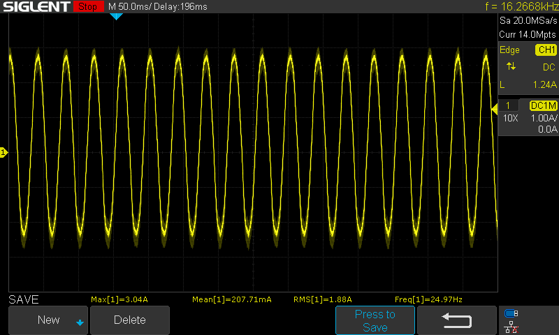
Additionally, I tuned the current controller, and the waveform I obtained is as follows:

Does this look good to you? Let me know if you need any more changes!
Options
- Mark as New
- Bookmark
- Subscribe
- Mute
- Subscribe to RSS Feed
- Permalink
- Email to a Friend
- Report Inappropriate Content
2024-09-04 8:52 AM
Hello carlos_gtronix.
From the screenshot it seems the current waveform is smooth without any jitter/noise; you may even try to increase the Kp/Ki of the current controllers (same values for Iq/Id for instance). Anyway, that is not your main concern for the time being. Are you using a custom motor prototype, is the datasheet available somewhere on the net?
Regarding the sensorless observer, it relies on its gain settings but also the correct entry of the motor parameters so that the estimate of the rotor speed can be rebuilt on the most accurate mathematical model of the motor.
Have you updated the file acim_motor_parameters.h that contains the parameters to customize the sensorless estimator to your application?
....
#define LM ((float)(0.1485)) /* Motor Magnetizing inductance (Dynamic model), (H) */
#define LR ((float)(0.1515)) /* Global rotor inductance (Dynamic model), Lr = Llr + LM, (H)*/
#define LS ((float)(0.1515)) /* Global stator inductance (Dynamic model), Ls = Lls + LM, (H)*/
#define TAU_R ((float)(0.2164286)) /* Rotor Time constant, Lr/Rr, (s) */
#define TAU_S ((float)(0.0688636)) /* Statot Time constant, Ls/Rs, (s) */
#define SIGMA ((float)(0.0392118)) /* Total leakage factor, (dimensionless)*/
#define POLE_PAIR_NUM 1 /* Number of motor pole pairs */
#define RS 2.2 /* Stator resistance , ohm*/
.....
This file contains by default the parameters for a legacy SELNI motor that is for sure different from the one you are using.
For instance, and as mentioned in my previous post, I would suggest to run your system with the tachometer giving the speed feedback of the rotor (so your system runs with the tacho sensor in sensor mode, not sensorless). Once running smoothly with the tacho sensor, you shall run the sensorless algo observer in parallel and monitor its output (still in sensor mode but with the sensorless code executed): from there you can check the actual rotor speed given by the tachometer and the rotor speed estimate given by the sensorless algo (to be tuned by updating the algo gains and probably the values in the file acim_motor_parameters.h). That will allow you to make sure the sensorless algo is running smoothly once the rotor speed estimate will be in line with the tacho speed physical sensor.
Please note also that at very low speed and low load (<>0 RPM <>0 current), it is where the sensorless algo is the most challenged : you may experience slight differences between the tacho feedback and the sensorless algo.
B.Rgds
Related Content
- 'undefined reference to..' error, after defining in main.h and creating a function. in STM32CubeIDE (MCUs)
- Current controller PI gains by SDK code generation looks different from what intended to be through space vector PWM in STM32 MCUs Motor control
- STM32F334: the new STM32 Digital-Power Microcontroller in STM32 MCUs Products