Turn on suggestions
Auto-suggest helps you quickly narrow down your search results by suggesting possible matches as you type.
Showing results for
- STMicroelectronics Community
- STM32 MCUs
- STM32 MCUs Motor control
- TImer 1 Break interrupt , false trigger
Options
- Subscribe to RSS Feed
- Mark Topic as New
- Mark Topic as Read
- Float this Topic for Current User
- Bookmark
- Subscribe
- Mute
- Printer Friendly Page
TImer 1 Break interrupt , false trigger
Options
- Mark as New
- Bookmark
- Subscribe
- Mute
- Subscribe to RSS Feed
- Permalink
- Email to a Friend
- Report Inappropriate Content
2023-03-15 04:10 AM
Hello Everyone,
I trying to develop customize BLDC motor control code on STEVAL-STPIN3204
Timer 1 - Ch 1 to Ch 3 - PWM signal drive
Ch 4 - No PWM output Mode
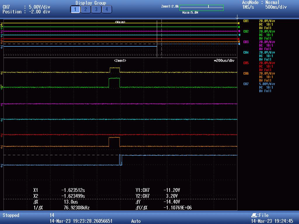
I am providing the some pulse to Gate drivers please refer the image 1.
After providing the pulse , and comparator 4 trigger then applied motor break , during motor break function , Timer 1 Break Interrupt Generated.
Break Function ()
{
TIM1->SR = ~(TIM_SR_UIF); // Clear the update Flag
TIM1->CCR1 = (uint32_t)0; // Clear the Pulse width 1
TIM1->CCR2 = (uint32_t)0; // Clear the Pulse width 2
TIM1->CCR3 = (uint32_t)0; // Clear the Pulse width 3
TIM1->CCR4 = (uint32_t)0; // Clear the Pulse width 4
TIM1->BDTR &= ~(TIM_BDTR_MOE); // Disable all output
TIM1->CCER &=(0xF555); // Reset the Channel Polarity
TIM1->EGR |= TIM_EGR_COMG; // Generate the event for execute the reset polarity (must required)
TIM1->BDTR |= TIM_BDTR_MOE; // Enable all output
}
IPD_pulse _Function()
{
((TIM1->CR1) &= ~((0x1UL << (0U))));
TIM1->CNT = 0;
TIM1->CCR1 = (uint32_t)0;
TIM1->CCR2 = (uint32_t)0;
TIM1->CCR3 = (uint32_t)0;
TIM1->CCR4 = (uint32_t)4150;
TIM1->BDTR &= ~(TIM_BDTR_MOE); // Disable all output
TIM1 -> CR1 &= ~TIM_CR1_UDIS;
TIM1->CCER &=(0xF555); // Reset the Channel Polarity
TIM1->EGR |= TIM_EGR_COMG; // Generate the event for execute the reset polarity (must required)
TIM1 -> CR1 |= TIM_CR1_UDIS;
(TIM1->CCER) |= ( LL_TIM_CHANNEL_CH1 | LL_TIM_CHANNEL_CH1N | LL_TIM_CHANNEL_CH2 | LL_TIM_CHANNEL_CH2N|LL_TIM_CHANNEL_CH3 | LL_TIM_CHANNEL_CH3N);
switch (commState)
{
case 1:
(TIM1->CCER) &= ~( LL_TIM_CHANNEL_CH1 |LL_TIM_CHANNEL_CH3 );
TIM1->CCER |= (LL_TIM_CHANNEL_CH2 | LL_TIM_CHANNEL_CH2N | LL_TIM_CHANNEL_CH1N | LL_TIM_CHANNEL_CH3N);
TIM1->CCR1 = (uint32_t)0;
TIM1->CCR2 = (uint32_t) IPD_PULSE;
TIM1->CCR3 = (uint32_t)0;
break;
case 2:
(TIM1->CCER) &= ~(LL_TIM_CHANNEL_CH2 );
TIM1->CCER |= (LL_TIM_CHANNEL_CH1 | LL_TIM_CHANNEL_CH3 | LL_TIM_CHANNEL_CH3N | LL_TIM_CHANNEL_CH2N | LL_TIM_CHANNEL_CH1N );
TIM1->CCR1 = (uint32_t)IPD_PULSE;
TIM1->CCR2 = (uint32_t)0;
TIM1->CCR3 = (uint32_t)IPD_PULSE;
break;
case 3:
(TIM1->CCER) &= ~( LL_TIM_CHANNEL_CH2 | LL_TIM_CHANNEL_CH1 );
TIM1->CCER |= ( LL_TIM_CHANNEL_CH2N | LL_TIM_CHANNEL_CH1N | LL_TIM_CHANNEL_CH3N | LL_TIM_CHANNEL_CH3);
TIM1->CCR1 = (uint32_t)0;
TIM1->CCR2 = (uint32_t)0;
TIM1->CCR3 = (uint32_t) IPD_PULSE ;
break;
case 4:
(TIM1->CCER) &= ~( LL_TIM_CHANNEL_CH3 );
TIM1->CCER |= (LL_TIM_CHANNEL_CH1 | LL_TIM_CHANNEL_CH2N | LL_TIM_CHANNEL_CH2 | LL_TIM_CHANNEL_CH1N | LL_TIM_CHANNEL_CH3N);
TIM1->CCR1 = (uint32_t)IPD_PULSE;
TIM1->CCR2 = (uint32_t)IPD_PULSE;
TIM1->CCR3 = (uint32_t)0;
break;
case 5:
(TIM1->CCER) &= ~( LL_TIM_CHANNEL_CH2 | LL_TIM_CHANNEL_CH3 );
TIM1->CCR1 = (uint32_t)IPD_PULSE;
TIM1->CCR2 = (uint32_t)0;
TIM1->CCR3 = (uint32_t)0;
TIM1->CCER |= (LL_TIM_CHANNEL_CH1 | LL_TIM_CHANNEL_CH2N | LL_TIM_CHANNEL_CH1N | LL_TIM_CHANNEL_CH3N);
break;
case 6:
(TIM1->CCER) &= ~( LL_TIM_CHANNEL_CH1);
TIM1->CCER |= (LL_TIM_CHANNEL_CH3 | LL_TIM_CHANNEL_CH2N | LL_TIM_CHANNEL_CH2 | LL_TIM_CHANNEL_CH1N | LL_TIM_CHANNEL_CH3N);
TIM1->CCR1 = (uint32_t)0;
TIM1->CCR2 = (uint32_t)IPD_PULSE;
TIM1->CCR3 = (uint32_t)IPD_PULSE;
break;
default:
break;
}
TIM1->EGR |= TIM_EGR_COMG; // Generate the event for execute the reset polarity (must required)
(TIM1->CR1) |= ((0x1UL << (0U)));
//TIM1->ARR = 0; // Set Auto Reload
TIM1->CNT = 0;
TIM1->RCR = 1;
TIM1 -> ARR = IPD_PULSE;
TIM1 -> CR1 &= ~TIM_CR1_UDIS;
TIM1 -> EGR = TIM_EGR_UG;
TIM1 -> CR1 |= TIM_CR1_UDIS;
TIM1->BDTR |= TIM_BDTR_MOE; // Enable all output
LL_TIM_SetTriggerOutput(TIM1, LL_TIM_TRGO_OC4REF); //Set the trigger output (TRGO) used for timer synchronization
TIM1->CCR4 = 3150; // Set the ADC R
TIM1->DIER |= TIM_DIER_CC4IE; // Enable interrupt on channel 4
LL_TIM_SetAutoReload(TIM1,4800); // set auto reload
}
Even i tried to remove the R44 resistor and C21 short to GND ,still at certain current level
Timer Break interrupt is Generated (please refer the schematic)
Please anyone can guide me for same?
Labels:
- Labels:
-
STM32 Motor Control
-
TIM
0 REPLIES 0
Related Content
- STM32 VS Code Extension generates startup file with unusable g_pfnVectors in STM32 VSCode extension (MCUs)
- STM32L432KC Timer interrupt only triggers once in STM32 MCUs Embedded software
- STM32H750 RAMECC Testing in STM32 MCUs Embedded software
- STM32 LPUART INTERRUPT IS NOT WORKING in STM32 MCUs Embedded software
- Generating a signal using DAC DMA transfer and simultaneous sampling and recording in STM32 MCUs products