Turn on suggestions
Auto-suggest helps you quickly narrow down your search results by suggesting possible matches as you type.
Showing results for
- STMicroelectronics Community
- STM32 MCUs
- STM32 MCUs Boards and hardware tools
- ADC value Oscillates form 0 to 151 even when the ...
Options
- Subscribe to RSS Feed
- Mark Topic as New
- Mark Topic as Read
- Float this Topic for Current User
- Bookmark
- Subscribe
- Mute
- Printer Friendly Page
ADC value Oscillates form 0 to 151 even when the ADC pin is grounded
Options
- Mark as New
- Bookmark
- Subscribe
- Mute
- Subscribe to RSS Feed
- Permalink
- Email to a Friend
- Report Inappropriate Content
2024-03-09 2:16 AM
/* USER CODE END Header */
/* Includes ------------------------------------------------------------------*/
#include "main.h"
/* Private includes ----------------------------------------------------------*/
/* USER CODE BEGIN Includes */
#include <string.h>
#include <stdio.h>
/* USER CODE END Includes */
/* Private typedef -----------------------------------------------------------*/
/* USER CODE BEGIN PTD */
/* USER CODE END PTD */
/* Private define ------------------------------------------------------------*/
/* USER CODE BEGIN PD */
/* USER CODE END PD */
/* Private macro -------------------------------------------------------------*/
/* USER CODE BEGIN PM */
/* USER CODE END PM */
/* Private variables ---------------------------------------------------------*/
ADC_HandleTypeDef hadc1;
UART_HandleTypeDef huart7;
/* USER CODE BEGIN PV */
/* USER CODE END PV */
/* Private function prototypes -----------------------------------------------*/
void SystemClock_Config(void);
static void MX_GPIO_Init(void);
static void MX_ADC1_Init(void);
static void MX_UART7_Init(void);
/* USER CODE BEGIN PFP */
/* USER CODE END PFP */
/* Private user code ---------------------------------------------------------*/
/* USER CODE BEGIN 0 */
uint32_t adc_val;
/* USER CODE END 0 */
/**
* @brief The application entry point.
* @retval int
*/
int main(void)
{
/* USER CODE BEGIN 1 */
uint16_t raw;
char msg[10];
/* USER CODE END 1 */
/* MCU Configuration--------------------------------------------------------*/
/* Reset of all peripherals, Initializes the Flash interface and the Systick. */
HAL_Init();
/* USER CODE BEGIN Init */
/* USER CODE END Init */
/* Configure the system clock */
SystemClock_Config();
/* USER CODE BEGIN SysInit */
/* USER CODE END SysInit */
/* Initialize all configured peripherals */
MX_GPIO_Init();
MX_ADC1_Init();
MX_UART7_Init();
/* USER CODE BEGIN 2 */
// HAL_ADC_Start(&hadc1, &buffer, 1);
/* USER CODE END 2 */
/* Infinite loop */
/* USER CODE BEGIN WHILE */
while (1)
{
/* USER CODE END WHILE */
/* USER CODE BEGIN 3 */
// Test: Set GPIO pin high
HAL_GPIO_WritePin(GPIOA, GPIO_PIN_0, GPIO_PIN_SET);
// Get ADC value
HAL_ADC_Start(&hadc1);
HAL_ADC_PollForConversion(&hadc1, HAL_MAX_DELAY);
raw = HAL_ADC_GetValue(&hadc1);
// Test: Set GPIO pin low
HAL_GPIO_WritePin(GPIOA, GPIO_PIN_0, GPIO_PIN_RESET);
// Convert to string and print
sprintf(msg, "%hu\r\n", raw);
HAL_UART_Transmit(&huart7, (uint8_t*)msg, strlen(msg), HAL_MAX_DELAY);
// Pretend we have to do something else for a while
HAL_Delay(100);
}
/* USER CODE END 3 */
}
/**
* @brief System Clock Configuration
* @retval None
*/
void SystemClock_Config(void)
{
RCC_OscInitTypeDef RCC_OscInitStruct = {0};
RCC_ClkInitTypeDef RCC_ClkInitStruct = {0};
/** Configure the main internal regulator output voltage
*/
__HAL_PWR_VOLTAGESCALING_CONFIG(PWR_REGULATOR_VOLTAGE_SCALE3);
while(!__HAL_PWR_GET_FLAG(PWR_FLAG_VOSRDY)) {}
/** Initializes the RCC Oscillators according to the specified parameters
* in the RCC_OscInitTypeDef structure.
*/
RCC_OscInitStruct.OscillatorType = RCC_OSCILLATORTYPE_HSI;
RCC_OscInitStruct.HSIState = RCC_HSI_ON;
RCC_OscInitStruct.HSIDiv = RCC_HSI_DIV2;
RCC_OscInitStruct.HSICalibrationValue = RCC_HSICALIBRATION_DEFAULT;
RCC_OscInitStruct.PLL.PLLState = RCC_PLL_NONE;
if (HAL_RCC_OscConfig(&RCC_OscInitStruct) != HAL_OK)
{
Error_Handler();
}
/** Initializes the CPU, AHB and APB buses clocks
*/
RCC_ClkInitStruct.ClockType = RCC_CLOCKTYPE_HCLK|RCC_CLOCKTYPE_SYSCLK
|RCC_CLOCKTYPE_PCLK1|RCC_CLOCKTYPE_PCLK2
|RCC_CLOCKTYPE_PCLK3;
RCC_ClkInitStruct.SYSCLKSource = RCC_SYSCLKSOURCE_HSI;
RCC_ClkInitStruct.AHBCLKDivider = RCC_SYSCLK_DIV1;
RCC_ClkInitStruct.APB1CLKDivider = RCC_HCLK_DIV1;
RCC_ClkInitStruct.APB2CLKDivider = RCC_HCLK_DIV1;
RCC_ClkInitStruct.APB3CLKDivider = RCC_HCLK_DIV1;
if (HAL_RCC_ClockConfig(&RCC_ClkInitStruct, FLASH_LATENCY_1) != HAL_OK)
{
Error_Handler();
}
}
/**
* @brief ADC1 Initialization Function
* @PAram None
* @retval None
*/
static void MX_ADC1_Init(void)
{
/* USER CODE BEGIN ADC1_Init 0 */
/* USER CODE END ADC1_Init 0 */
ADC_ChannelConfTypeDef sConfig = {0};
/* USER CODE BEGIN ADC1_Init 1 */
/* USER CODE END ADC1_Init 1 */
/** Common config
*/
hadc1.Instance = ADC1;
hadc1.Init.ClockPrescaler = ADC_CLOCK_ASYNC_DIV1;
hadc1.Init.Resolution = ADC_RESOLUTION_12B;
hadc1.Init.DataAlign = ADC_DATAALIGN_RIGHT;
hadc1.Init.ScanConvMode = ADC_SCAN_DISABLE;
hadc1.Init.EOCSelection = ADC_EOC_SINGLE_CONV;
hadc1.Init.LowPowerAutoWait = DISABLE;
hadc1.Init.ContinuousConvMode = DISABLE;
hadc1.Init.NbrOfConversion = 1;
hadc1.Init.DiscontinuousConvMode = DISABLE;
hadc1.Init.ExternalTrigConv = ADC_SOFTWARE_START;
hadc1.Init.ExternalTrigConvEdge = ADC_EXTERNALTRIGCONVEDGE_NONE;
hadc1.Init.DMAContinuousRequests = DISABLE;
hadc1.Init.SamplingMode = ADC_SAMPLING_MODE_NORMAL;
hadc1.Init.Overrun = ADC_OVR_DATA_PRESERVED;
hadc1.Init.OversamplingMode = DISABLE;
if (HAL_ADC_Init(&hadc1) != HAL_OK)
{
Error_Handler();
}
/** Configure Regular Channel
*/
sConfig.Channel = ADC_CHANNEL_0;
sConfig.Rank = ADC_REGULAR_RANK_1;
sConfig.SamplingTime = ADC_SAMPLETIME_2CYCLES_5;
sConfig.SingleDiff = ADC_SINGLE_ENDED;
sConfig.OffsetNumber = ADC_OFFSET_NONE;
sConfig.Offset = 0;
if (HAL_ADC_ConfigChannel(&hadc1, &sConfig) != HAL_OK)
{
Error_Handler();
}
/* USER CODE BEGIN ADC1_Init 2 */
/* USER CODE END ADC1_Init 2 */
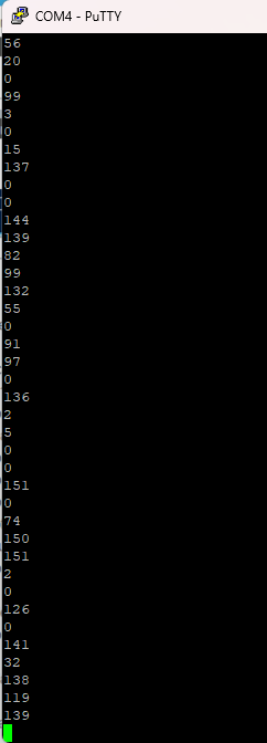
I'm using STM32H563ZIT6 (Nucleo Board) and configured a single ADC input pin PA0, with a frequency of 32MHz and the following configuration as in image. However, when the ADC pin is connected to ground, the ADC value oscillates between 0 and 152 ADC counts. Please help me to solve this issue.
Labels:
- Labels:
-
STM32H5 Series
4 REPLIES 4
Options
- Mark as New
- Bookmark
- Subscribe
- Mute
- Subscribe to RSS Feed
- Permalink
- Email to a Friend
- Report Inappropriate Content
2024-03-09 3:57 AM
Hi,
you have to run calibration on ADC first ! (read in rm! )
HAL_ADCEx_Calibration_Start(..);
If you feel a post has answered your question, please click "Accept as Solution".
Options
- Mark as New
- Bookmark
- Subscribe
- Mute
- Subscribe to RSS Feed
- Permalink
- Email to a Friend
- Report Inappropriate Content
2024-03-09 4:36 AM
Thanks for the reply, I have calibrated the ADC as you mentioned and the results are better but still I'm getting the ADC value up to 96.
if (HAL_ADCEx_Calibration_Start(&hadc1, ADC_SINGLE_ENDED) == HAL_OK)
{
HAL_UART_Transmit(&huart7, (uint8_t*)"Successfull", 12, HAL_MAX_DELAY);
}
I'm working in a project where I need to configure 14 ADC pins, so I have actually configured 14 ADC pins using DMA, but in 11 ADC pins I'm facing the same issue (Getting oscillating ADC value up to 200 ADC counts). So I have created a new project and configured only a single ADC pin (without DMA) and posted earlier.
As for the remaining 3 ADC pins,
1. In two ADC pins (PC4 & PC5) - The voltage of sensor output pin is reduced when connected to the ADC pin of the STM32H563 controller.
2. In last ADC pin (PA2) - The voltage of sensor output pin is Increased when connected to the ADC pin of the STM32H563 controller.
But when i give 3.3v to the ADC pins, i got 4095 (12 bit max value) from all 14 ADC pins.
Options
- Mark as New
- Bookmark
- Subscribe
- Mute
- Subscribe to RSS Feed
- Permalink
- Email to a Friend
- Report Inappropriate Content
2024-03-09 5:36 AM
Ok, so next "problem" : you set very short sampling time, this works only on low impedance input.
-> read in ds...

and set longer sampling time or (if slow signal or DC ) a big cer.cap (100nF or so) on short connection adc-input to gnd.
If still "Getting oscillating ADC value" look with a scope on adc-input pin - maybe adc is right. :)
If you feel a post has answered your question, please click "Accept as Solution".
Options
- Mark as New
- Bookmark
- Subscribe
- Mute
- Subscribe to RSS Feed
- Permalink
- Email to a Friend
- Report Inappropriate Content
2024-03-11 10:21 PM
Sorry for the delay, I have increased the sampling time every steps up to 640.5 cycles but the still the ADC value is oscillating as earlier.
I have checked the Vref+ and VDDA pin voltage on scope and the voltage varies from 3.28V to 3.3V and On ground pin the voltage is zero but there is a noise with voltage of 80mV which is around 100 ADC count.
In Errata sheet of this controller, I can't find any issue on the GND pin.
Related Content
- Clarification on Crystal Oscillators in STM32L432KCU6 in STM32 MCUs Products
- STSPINF0251 Not spinning BLDC motor in STM32 MCUs Motor control
- STM32 HyperRAM Memory access issue in STM32 MCUs Products
- Using OCXO as an External Oscillator for STM32H533 in STM32 MCUs Products
- Custom STSPIN32 Board flashing not working in STM32 MCUs Motor control