Turn on suggestions
Auto-suggest helps you quickly narrow down your search results by suggesting possible matches as you type.
Showing results for
- STMicroelectronics Community
- Product forums
- Power management
- Re: 4 full bridges in parallel using 2 L6206 devic...
Options
- Subscribe to RSS Feed
- Mark Topic as New
- Mark Topic as Read
- Float this Topic for Current User
- Bookmark
- Subscribe
- Mute
- Printer Friendly Page
4 full bridges in parallel using 2 L6206 devices.
Options
- Mark as New
- Bookmark
- Subscribe
- Mute
- Subscribe to RSS Feed
- Permalink
- Email to a Friend
- Report Inappropriate Content
2020-11-25 5:55 AM
Hello
I need to put 4 full bridges in parallel to avoid excessive heat of the L6206
My design is based on figure 15 of the datasheet :
- half bridge 1A connected with half bridge 1B ( pin OUT and pin IN)
- half bridge 2A connected with half bridge 2B ( pin OUT and pin IN)
The same is done with the second device, half bridge 1A-1B of both devices are connected together. Half bridge 2A-2B of both devices are connected together.
The 4RCL resistor are 15k resistor. ( 1.5A for each bridge)
Each OCD pin are connected together
The result should be one full bridge which should allow a current of 6A.
But the current limiting seems not to work correctly. The current is limited to 4.2A in PWM:
IN1A is connected to 5V and a PWM is applied to IN2A. On each rising edge of the PWM ( end of the active phase of the PWM), the OCD make the signal on the Enable pins go down during 300ns. Then the voltage on the Enable pin rises slowly until the next rising edge of the PWM
If I connect IN2A to gnd instead of using a PWM, the current limiting works fine, with a current limited to 5.8A
Has anyone tried to put bridges from different devices in parallel, like I did?
Solved! Go to Solution.
Labels:
- Labels:
-
Motor Control Hardware
1 ACCEPTED SOLUTION
Accepted Solutions
Options
- Mark as New
- Bookmark
- Subscribe
- Mute
- Subscribe to RSS Feed
- Permalink
- Email to a Friend
- Report Inappropriate Content
2020-12-17 7:35 AM
Hello @Fabrice Comby,
after an internal discussion I realized that it is possible to put bridges from different devices in parallel but with some proper measures.
The observed behavior is due to the timings mismatch (propagation delays, dead time and so on) between the two different device.
My previous observations were incorrectly related to the high-side current mirroring in both directions.
>> IN1A is connected to 5V and a PWM is applied to IN2A.
In this case, due to the different switching characteristics, at the PWM rising edge one of the two devices is bringing the total motor current that triggers the protection.
>> If I connect IN2A to gnd.
In this configuration you are not bound by the timings mismatch.
So, if you want to parallel different devices you have to compensate the effects of timings mismatch.
For example you could try to add a small inductance (an order of magnitude smaller than the motor inductance) in series to each two half-bridge output of same devices:

This configuration must be verify with bench tests.
Finally some comments to make order:
- the over current threshold is set with resistor connected to RCLx pins. With RCL=15 khom, the OCD threshold for each device is about 3 A --> total OCD threshold 6A.
- the RC network on ENx pins set the disable time (time before recovering normal operation after an OC event) and the delay time (time before turning off the bridge after an OC event). With 15 kohm and 33 nF (high level at 5V) you have a delay time ≈ 2.9 us and disable time ≈ 112 us. Recommended values for REN and CEN are respectively 100 kohm and 5.6 nF that allow obtaining 200 us disable time and 1 us.
Let me know if I solved your doubts ;)
If you feel a post has answered your question, please click "Accept as Solution"
9 REPLIES 9
Options
- Mark as New
- Bookmark
- Subscribe
- Mute
- Subscribe to RSS Feed
- Permalink
- Email to a Friend
- Report Inappropriate Content
2020-11-26 12:38 AM
Hello @Fabrice Comby welcome to ST Community.
In parallel connection, based on Figure 15 of the L6206 datasheet, each device have doubled OCD threshold.
In your case, with 15 kohm of RCL, the OCD threshold for each one is about 3 A.
The OCD protection (refer to dedicated section in the datasheet starting at page 13) works sensing the current in each high-side power MOS.
The sum of the current of each power is compared with the reference one generated according to RCL value.
>> IN1A is connected to 5V and a PWM is applied to IN2A.
With this configuration when both high-side is turned on, the current used for the comparison is twice the load current.(*) The higher value of load current (4.2 A) that you measured, could be related to two factors: the OCD threshold precision (nominal value ±10%) and the delay time of protection intervention.
Concerning the timings, what are the RC network values connected to EN pins?
With RC value you can set the disable time (time before recovering normal operation after an OC event) and the delay time (time before turning off the bridge after an OC event).
>> If I connect IN2A to gnd.
In this configuration you are reading the load current in a single high-side.
Assuming a fair distribution between the L6206 the measured load current is equal to the expected limit.
Let me know if these info have been useful to you to understand the different behavior.
(*) Edit: refer to the following post.
If you feel a post has answered your question, please click "Accept as Solution"
Options
- Mark as New
- Bookmark
- Subscribe
- Mute
- Subscribe to RSS Feed
- Permalink
- Email to a Friend
- Report Inappropriate Content
2020-11-27 2:40 AM
Hello,
My RC network values are : Ren = 15kohms and Cen = 33nF.
What you describe in your email is the behaviour of the 2 bridges of the same device in parallel.
In my case, I do it on 2 different devices.
And then, I connect the 2 devices together, in parallel : All En pins are connected together, INA1 of each device connected together, INA2 of each device connected together...
So I have four full bridges in parallel.
So the 4.2A I measured is not a higher value, but a lower value.
With RCL = 15kohms, I should have 3A for each device, and 6A when the 2 devices are connected together.
When I connect IN2A to ground, I can see that the limitation is made at the correct value : 5.8A
What I don't understand is : Why do I have the expected result with a continuous drive, but not when I apply a PWM on IN2A?
Is it because we can't connect in parallel 2 bridges of different devices?
Thank you for your help
Options
- Mark as New
- Bookmark
- Subscribe
- Mute
- Subscribe to RSS Feed
- Permalink
- Email to a Friend
- Report Inappropriate Content
2020-11-27 3:20 AM
Hello @Fabrice Comby,
first of all, yes you can parallel 2 bridges of different devices.
In my previous post I described what happens inside each device.
Putting in parallel 2 devices the load current is shared almost equally in the power stage thanks to the good matching of RDS(ON) value.
But the reference current value for the OCD protection is still 3A for each device is not four times the set one. (*)
You can parallel the power bridge of different device but the OCD works independently for each device.
When you say you see the limitation to 5.8A, you’re talking about total motor current, right?
Connecting the IN2A to ground each device will see about 3A and trigger the protection properly.
On the other hand applying PWM on IN2A, when both high-side is turned on the current used for the comparison is twice the load current and the reference one is always 3A.
Let me know if I made myself clear ;)
(*) Edit: refer to the following post.
If you feel a post has answered your question, please click "Accept as Solution"
Options
- Mark as New
- Bookmark
- Subscribe
- Mute
- Subscribe to RSS Feed
- Permalink
- Email to a Friend
- Report Inappropriate Content
2020-11-30 9:17 AM
Hello,
OK, with the Ren resistor I use, The OCD protection should be 3A for each device.
Yes, When I said I saw a limitation to 5.8A, I was talking about the total current. ( The sum of the currents of the 2 devices)
I am not sure to understand the following paragraph. You said :
" On the other hand applying PWM on IN2A, when both high-side is turned on the current used for the comparison is twice the load current and the reference one is always 3A."
In my configuration, four full bridges (2 on each device) are connected in parallel, with limitation to 1.5A on each bridge. I apply 5V on all INB pins and the same PWM on each INA pin.
You said that, in my configuration, when I apply a PWM on INA , the comparison is twice the load current and the reference one is always 3A.
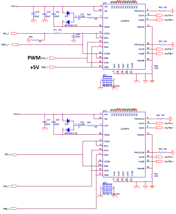
To be sure that we understand eachother, I have joined the drawing showing the connection of the 2 L6206 devices.
I have also joined the chronogram at the precise time the OCD signal detects overcurrent (total current in the load driven by the 4 :
- in pink, the current
- in yellow, the OCD signal
- In blue, the INA signal (PWM 10kHz). The INB pins are connected to +5V.
We see that 700ns after INA rises, the OCD signal decreases during 300ns, whereas the total current(device1 + device2) is only 4.5A.
I guess that these 700ns is the turn off delay time of the H bridge (600ns typical according to datasheet).
Is there anything wrong with my scheme?
To be able to have 6A(total current in the load: device1 + device 2), should I configure Ren ( R71 on my scheme) to enable 3A on each bridge?
Options
- Mark as New
- Bookmark
- Subscribe
- Mute
- Subscribe to RSS Feed
- Permalink
- Email to a Friend
- Report Inappropriate Content
2020-11-30 9:17 AM
Options
- Mark as New
- Bookmark
- Subscribe
- Mute
- Subscribe to RSS Feed
- Permalink
- Email to a Friend
- Report Inappropriate Content
2020-12-17 7:35 AM
Hello @Fabrice Comby,
after an internal discussion I realized that it is possible to put bridges from different devices in parallel but with some proper measures.
The observed behavior is due to the timings mismatch (propagation delays, dead time and so on) between the two different device.
My previous observations were incorrectly related to the high-side current mirroring in both directions.
>> IN1A is connected to 5V and a PWM is applied to IN2A.
In this case, due to the different switching characteristics, at the PWM rising edge one of the two devices is bringing the total motor current that triggers the protection.
>> If I connect IN2A to gnd.
In this configuration you are not bound by the timings mismatch.
So, if you want to parallel different devices you have to compensate the effects of timings mismatch.
For example you could try to add a small inductance (an order of magnitude smaller than the motor inductance) in series to each two half-bridge output of same devices:
This configuration must be verify with bench tests.
Finally some comments to make order:
- the over current threshold is set with resistor connected to RCLx pins. With RCL=15 khom, the OCD threshold for each device is about 3 A --> total OCD threshold 6A.
- the RC network on ENx pins set the disable time (time before recovering normal operation after an OC event) and the delay time (time before turning off the bridge after an OC event). With 15 kohm and 33 nF (high level at 5V) you have a delay time ≈ 2.9 us and disable time ≈ 112 us. Recommended values for REN and CEN are respectively 100 kohm and 5.6 nF that allow obtaining 200 us disable time and 1 us.
Let me know if I solved your doubts ;)
If you feel a post has answered your question, please click "Accept as Solution"
Options
- Mark as New
- Bookmark
- Subscribe
- Mute
- Subscribe to RSS Feed
- Permalink
- Email to a Friend
- Report Inappropriate Content
2020-12-23 12:55 AM
Hello @Cristiana Scaramel_O
That's what I feared. The timings mismatch have to be compensated.
Thank you for your help
Concerning the value of the RC network on ENx pin, the recommended value is 100kohms.
But, the datasheet gives a low level logic input current of 10µA.

If we apply this on the Enx pin, this means that the voltage across the REN resistor could be 100kohms x 10µA = 1V
In my case, as I use 4 bridges in parallel, the 4 Enx pins are tied together and my input current could be 4x10µA = 40µA.
I could have 4V accross the REN resistor. This value is much higher than the Low level input Voltage(0.8V)! That's why I used a smaller resistor.
But perhaps I'm wrong and the ENx pin is not considered as a logic input ? So I could keep the 100kohms resistor?
Options
- Mark as New
- Bookmark
- Subscribe
- Mute
- Subscribe to RSS Feed
- Permalink
- Email to a Friend
- Report Inappropriate Content
2021-01-07 3:23 AM
Hello @Fabrice Comby and happy New Year.
To reduce the timings mismatch effects you could parallel all half-bridges of a single device to drive one side of the motor and another L6206 to drive the other side (refer to L6206 datasheet at page 20 Figure 17).
Concerning the low logic level current I checked the parameters distributions for both EN pins and the measured current is about zero (some tens of nA).
I agree that the limit in the datasheet is misleading, anyway I confirm my suggestion to use 100 kohm and 5.6 nF for RC network on the enable pins.
If we can consider closed this topic please "Select as Best" button in the proper reply for the original question.
If you feel a post has answered your question, please click "Accept as Solution"
Options
- Mark as New
- Bookmark
- Subscribe
- Mute
- Subscribe to RSS Feed
- Permalink
- Email to a Friend
- Report Inappropriate Content
2021-01-07 3:44 AM
Hello @Cristiana SCARAMEL
Happy New Year!
Thank you for your help!
We can close this topic.
Related Content
- OCTOSPI as simple QUAD/Dual/Single parallel-to-serial output on STM32H5xx in STM32 MCUs Products
- 20 MSPS 8-bit External ADC on STM32H7R3V8T6 in STM32 MCUs Products
- STM32MP157 Change LTDC_CLK frequency after wakeup from deep suspend in STM32 MPUs Products
- STWBC2-HP Qi transmitter and CC Handling with Macbook Pro M1 and Mac Mini while using USB data lines in Power management
- STM32 Cube Programmer CLI - Device Listing Command Bug in STM32CubeProgrammer (MCUs)