Turn on suggestions
Auto-suggest helps you quickly narrow down your search results by suggesting possible matches as you type.
Showing results for
- STMicroelectronics Community
- MEMS and sensors
- Imaging (sensors)
- Integration of multiple VL53L0X
Options
- Subscribe to RSS Feed
- Mark Topic as New
- Mark Topic as Read
- Float this Topic for Current User
- Bookmark
- Subscribe
- Mute
- Printer Friendly Page
Integration of multiple VL53L0X
Options
- Mark as New
- Bookmark
- Subscribe
- Mute
- Subscribe to RSS Feed
- Permalink
- Email to a Friend
- Report Inappropriate Content
2024-08-05 09:23 PM
Dear ST,
I am looking for a solution with the integration of multiple ToFs such as VL53L0x
Objective:
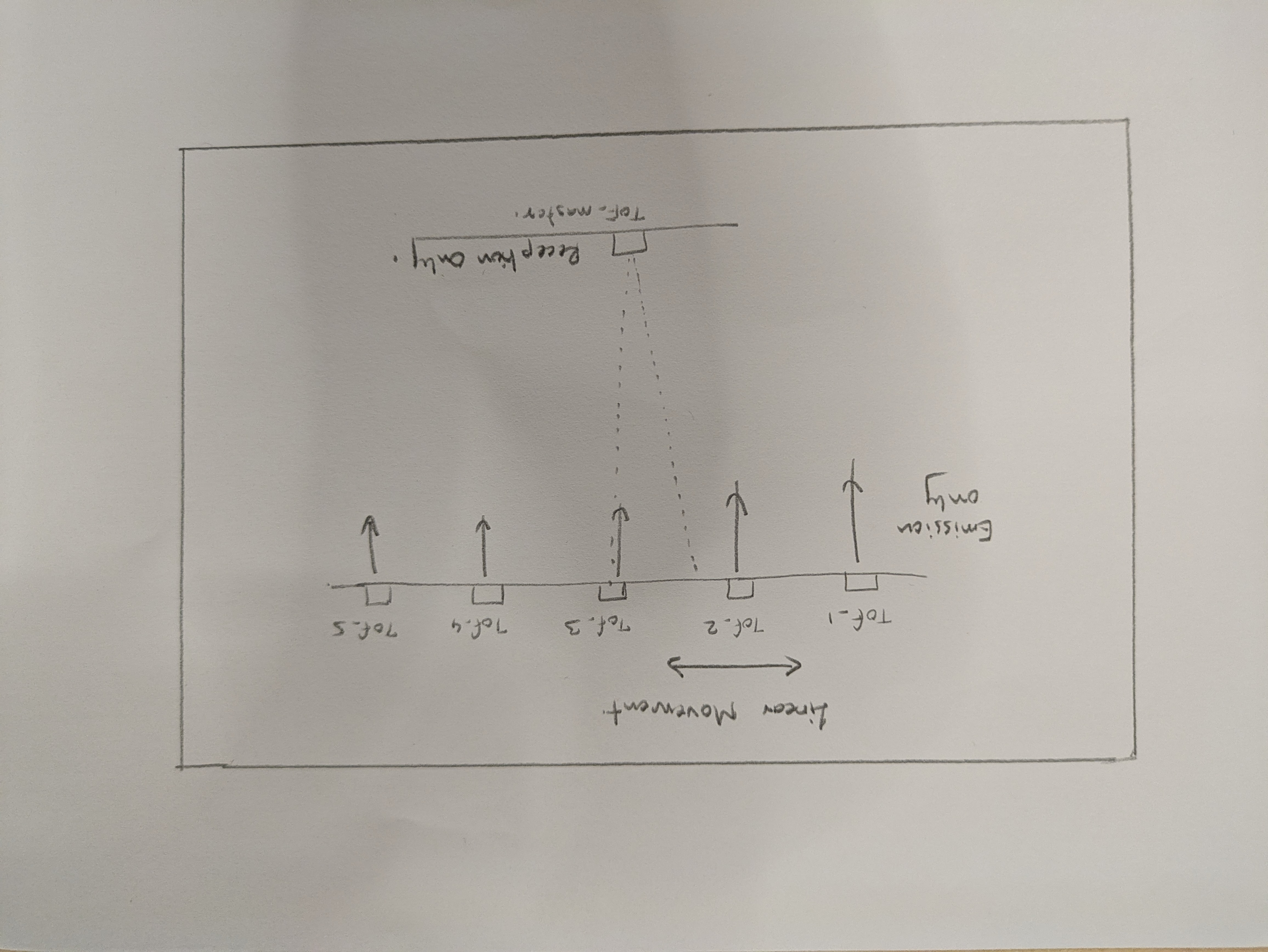
1. Find the distance between the ToF_x(emission only) and ToF_master(reception only)
As the reception zone of vl53l0x is 25 degrees , either one or multiple ToFs could be detected with distance
(NOTE : During operation either of ToF_x will be in linear movement to fall in reception zone )
Setup:
ToF_1 ToF_2 ToF_3 ToF_4
| |
| |
| |
ToF_master
Questions:
1. Do we have the provisions in firmware to control the vl53l0x emission and reception part separately ?
2. Open to explore other ToFs as well helping to solving this solve this issue asap
Please refer attached image for setup idea
Thanks
Labels:
- Labels:
-
Ambient light
-
Time of flight
2 REPLIES 2
Options
- Mark as New
- Bookmark
- Subscribe
- Mute
- Subscribe to RSS Feed
- Permalink
- Email to a Friend
- Report Inappropriate Content
2024-08-06 07:22 AM
One of the reasons the VL53 sensors work is that the transmit side is so closely coupled to the receiver side. We don't even count on the power 'on' to start the process. The start time is when the VCSEL (laser) starts emitting and some photons hit our reference array. This gives us much better timing.
Another thing to know is that during that 30ms range, there are many, many (call it a million) individual pulses emitted by the sensor.
And then there is the issue of spread-spectrum. If all those pulses were started at a constant frequency, the EMI emitted by the chip would ruin any near-by parts. So, we dither the clock to spread the energy out and avoid a single frequency noise.
Add all that stuff up and basically you cannot do what you propose. Not with this chip anyway. The sensor is just too integrated to be able to take it apart as you suggest.
And, of course, there are no sync pins.
But I do like the concept. But you are going to need something like what is in a commercial Range finder (Bosch makes one). It has a separate VCSEL, VCSEL driver, SPAD (Single Photon Avalanche Diode) array to detect the photons and a separate MCU - TI makes one.
But your biggest challenge is going to be how to synchronize the system. The accuracy of your circuit is going to be the hard bit.
If this or any post solves your issue, please mark them as 'Accept as Solution' It really helps. And if you notice anything wrong do not hesitate to 'Report Inappropriate Content'. Someone will review it.
Options
- Mark as New
- Bookmark
- Subscribe
- Mute
- Subscribe to RSS Feed
- Permalink
- Email to a Friend
- Report Inappropriate Content
2024-08-07 12:06 PM
Thanks John ,
Please care to help me understand the following
1. The Biggest challenge to synchronize and accuracy would be tricky part to be solved
2. If we follow along the separate parts such as VCSEL and SPAD ( Emission and Reception part) , finding the distance based on only detection
Would be much more trickier than the point 1 itself (as Interference, Reflection, Intensity would come into play , that ST had already solved in a best possible way )
Question:
1. Considering VL53L8CH as reception part, Block the Emission part (Using Opaque/Absorbing material)
While other VL53L8CH as Emission only, and this entire setup is tightly synced
Does every device has unique IR radiation pattern ?
2. Is there a diffraction lens or material upon which ToF sensor measures it , but gives a unique pattern (distinguishable from surrounding)
Thanks
Related Content
- Multiple VL53L0X sensors for bluepill board in Imaging (sensors)
- maximum temperature (while not operational) of VL53L0X ToF sensor in Imaging (sensors)
- How does a VL53L0X react with multiple targets in FOV in Imaging (sensors)
- VL53L0X API: Usage of the 6 limit checks, Ambient SPAD damper, Dmax Cal, etc in Imaging (sensors)