seppeltronics_v
Associate III
April 4, 2023
Question

CAN-Bus no callback/received frame; FDCAN STM32G474

  • April 4, 2023
  • 22 replies
  • 12999 views

Hello,

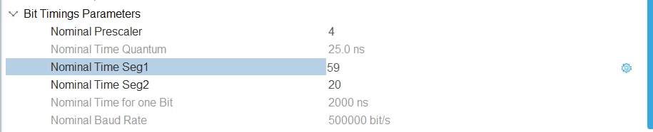
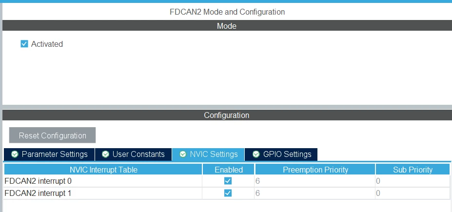
when I try to receive a CAN-Frame it is not received by the Microcontroller, it is within the range, I have no idea what the issue is.

Thanks to everybody in advance, Best Regards, Seppel
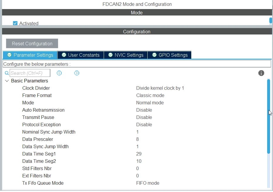
0693W00000bhUdqQAE.png0693W00000bhUe5QAE.png 

0693W00000bhUeFQAU.png 

void FDCAN_Config(FDCAN_HandleTypeDef *pHfdcan)
{
 
 pHandleToFdCan = pHfdcan;
 
 /* Configure Rx filter */
 sFilterConfig.IdType = FDCAN_STANDARD_ID;
 sFilterConfig.FilterIndex = 0;
 sFilterConfig.FilterType = FDCAN_FILTER_RANGE;
 sFilterConfig.FilterConfig = FDCAN_FILTER_TO_RXFIFO0;
 sFilterConfig.FilterID1 = 0x700;
 sFilterConfig.FilterID2 = 0x7FF;
 if (HAL_FDCAN_ConfigFilter(pHandleToFdCan, &sFilterConfig) != HAL_OK)
 {
 Error_Handler();
 }
 
 /* Configure global filter:
 Filter all remote frames with STD and EXT ID
 Reject non matching frames with STD ID and EXT ID */
 if (HAL_FDCAN_ConfigGlobalFilter(pHandleToFdCan, FDCAN_REJECT, FDCAN_REJECT, FDCAN_REJECT, FDCAN_REJECT) != HAL_OK)
 {
 Error_Handler();
 }


 /* Start the FDCAN module */
 if (HAL_FDCAN_Start(pHandleToFdCan) != HAL_OK)
 {
 Error_Handler();
 }
 
 if (HAL_FDCAN_ActivateNotification(pHandleToFdCan, FDCAN_IT_RX_FIFO0_NEW_MESSAGE, 0) != HAL_OK)
 {
 Error_Handler();
 }
 
}
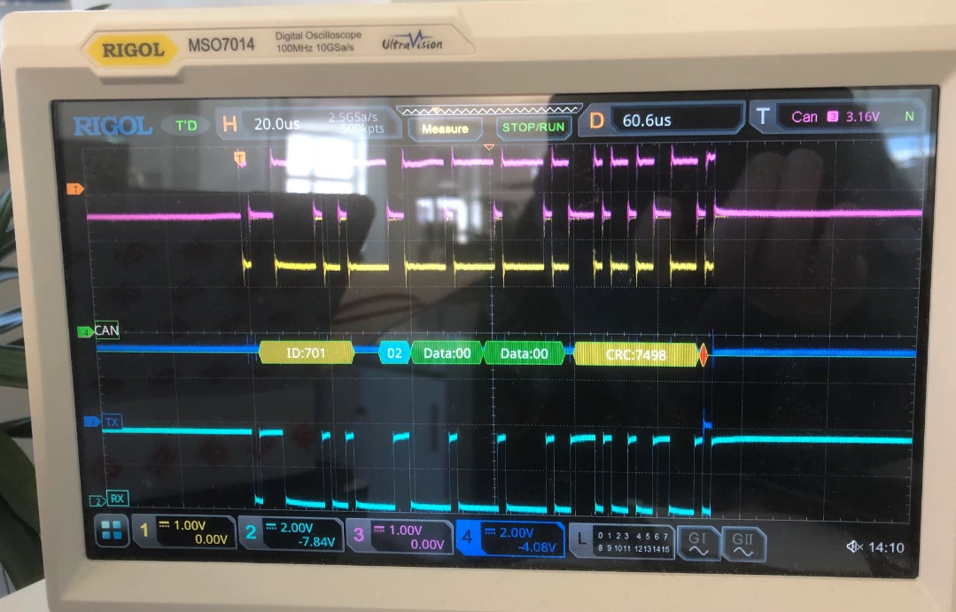
0693W00000bhUf3QAE.png 

P.S. TX works perfectly fine, as you can see it Ack's the 0x701 Frame that was received.

This topic has been closed for replies.

22 replies

AndrewST
Associate II
April 4, 2023

Can you show the "when I try to receive a CAN-Frame" part of your code? What does your callback function look like?

seppeltronics_v
Associate III
April 4, 2023

Hello,

as far as I'm aware the Function "HAL_FDCAN_RxFifo0Callback" needs to be implemented, which I did, I set a breakpoint, but it is never involked. "HAL_FDCAN_IRQHandler" is also never invoked.

void HAL_FDCAN_RxFifo0Callback(FDCAN_HandleTypeDef *phfdcan, uint32_t RxFifo0ITs)
{
 if((RxFifo0ITs & FDCAN_IT_RX_FIFO0_NEW_MESSAGE) != RESET)
 {
 /* Retrieve Rx messages from RX FIFO0 */
 if (HAL_FDCAN_GetRxMessage(phfdcan, FDCAN_RX_FIFO0, &RxHeader, RxData) != HAL_OK)
 {
 Error_Handler();
 }
 else
 {
 // HAL_Ok
 if ((RxHeader.DataLength == CanMsgLen_Pressure)&&(RxHeader.Identifier == CanMsgId_Control))
 {
 canSendData = RxData[0U];
 }
 
 }
 
 }
}

Best Regards, Seppel

AndrewST
Associate II
April 4, 2023

That looks about right.

How about your receive buffers configuration?

0693W00000bhVJhQAM.png

seppeltronics_v
Associate III
April 4, 2023

Hello,

there is no "Receive Buffer Configuration" in the IDE. How did you find it for the STM32G474?

I think there are 3 RX Buffers for the controller if I remember right, but I have no idea how to configure these and I have not found examples wher it is done.

Best Regards, Seppel

P.S. Nothing about RX-Buffers in the generated fdcan.c file.

/* USER CODE BEGIN Header */
/**
 ******************************************************************************
 * @file fdcan.c
 * @brief This file provides code for the configuration
 * of the FDCAN instances.
 ******************************************************************************
 * @attention
 *
 * Copyright (c) 2023 STMicroelectronics.
 * All rights reserved.
 *
 * This software is licensed under terms that can be found in the LICENSE file
 * in the root directory of this software component.
 * If no LICENSE file comes with this software, it is provided AS-IS.
 *
 ******************************************************************************
 */
/* USER CODE END Header */
/* Includes ------------------------------------------------------------------*/
#include "fdcan.h"
 
/* USER CODE BEGIN 0 */
 
/* USER CODE END 0 */
 
FDCAN_HandleTypeDef hfdcan2;
 
/* FDCAN2 init function */
void MX_FDCAN2_Init(void)
{
 
 /* USER CODE BEGIN FDCAN2_Init 0 */
 
 /* USER CODE END FDCAN2_Init 0 */
 
 /* USER CODE BEGIN FDCAN2_Init 1 */
 
 /* USER CODE END FDCAN2_Init 1 */
 hfdcan2.Instance = FDCAN2;
 hfdcan2.Init.ClockDivider = FDCAN_CLOCK_DIV1;
 hfdcan2.Init.FrameFormat = FDCAN_FRAME_CLASSIC;
 hfdcan2.Init.Mode = FDCAN_MODE_NORMAL;
 hfdcan2.Init.AutoRetransmission = DISABLE;
 hfdcan2.Init.TransmitPause = DISABLE;
 hfdcan2.Init.ProtocolException = DISABLE;
 hfdcan2.Init.NominalPrescaler = 4;
 hfdcan2.Init.NominalSyncJumpWidth = 1;
 hfdcan2.Init.NominalTimeSeg1 = 59;
 hfdcan2.Init.NominalTimeSeg2 = 20;
 hfdcan2.Init.DataPrescaler = 8;
 hfdcan2.Init.DataSyncJumpWidth = 1;
 hfdcan2.Init.DataTimeSeg1 = 29;
 hfdcan2.Init.DataTimeSeg2 = 10;
 hfdcan2.Init.StdFiltersNbr = 0;
 hfdcan2.Init.ExtFiltersNbr = 0;
 hfdcan2.Init.TxFifoQueueMode = FDCAN_TX_FIFO_OPERATION;
 if (HAL_FDCAN_Init(&hfdcan2) != HAL_OK)
 {
 Error_Handler();
 }
 /* USER CODE BEGIN FDCAN2_Init 2 */
 
 /* USER CODE END FDCAN2_Init 2 */
 
}
 
void HAL_FDCAN_MspInit(FDCAN_HandleTypeDef* fdcanHandle)
{
 
 GPIO_InitTypeDef GPIO_InitStruct = {0};
 RCC_PeriphCLKInitTypeDef PeriphClkInit = {0};
 if(fdcanHandle->Instance==FDCAN2)
 {
 /* USER CODE BEGIN FDCAN2_MspInit 0 */
 
 /* USER CODE END FDCAN2_MspInit 0 */
 
 /** Initializes the peripherals clocks
 */
 PeriphClkInit.PeriphClockSelection = RCC_PERIPHCLK_FDCAN;
 PeriphClkInit.FdcanClockSelection = RCC_FDCANCLKSOURCE_PCLK1;
 if (HAL_RCCEx_PeriphCLKConfig(&PeriphClkInit) != HAL_OK)
 {
 Error_Handler();
 }
 
 /* FDCAN2 clock enable */
 __HAL_RCC_FDCAN_CLK_ENABLE();
 
 __HAL_RCC_GPIOB_CLK_ENABLE();
 /**FDCAN2 GPIO Configuration
 PB5 ------> FDCAN2_RX
 PB6 ------> FDCAN2_TX
 */
 GPIO_InitStruct.Pin = RXD_CanTransceiver_Pin|TXD_CanTransceiver_Pin;
 GPIO_InitStruct.Mode = GPIO_MODE_AF_PP;
 GPIO_InitStruct.Pull = GPIO_NOPULL;
 GPIO_InitStruct.Speed = GPIO_SPEED_FREQ_VERY_HIGH;
 GPIO_InitStruct.Alternate = GPIO_AF9_FDCAN2;
 HAL_GPIO_Init(GPIOB, &GPIO_InitStruct);
 
 __HAL_SYSCFG_FASTMODEPLUS_ENABLE(SYSCFG_FASTMODEPLUS_PB6);
 
 /* FDCAN2 interrupt Init */
 HAL_NVIC_SetPriority(FDCAN2_IT0_IRQn, 1, 0);
 HAL_NVIC_EnableIRQ(FDCAN2_IT0_IRQn);
 HAL_NVIC_SetPriority(FDCAN2_IT1_IRQn, 1, 0);
 HAL_NVIC_EnableIRQ(FDCAN2_IT1_IRQn);
 /* USER CODE BEGIN FDCAN2_MspInit 1 */
 
 /* USER CODE END FDCAN2_MspInit 1 */
 }
}
 
void HAL_FDCAN_MspDeInit(FDCAN_HandleTypeDef* fdcanHandle)
{
 
 if(fdcanHandle->Instance==FDCAN2)
 {
 /* USER CODE BEGIN FDCAN2_MspDeInit 0 */
 
 /* USER CODE END FDCAN2_MspDeInit 0 */
 /* Peripheral clock disable */
 __HAL_RCC_FDCAN_CLK_DISABLE();
 
 /**FDCAN2 GPIO Configuration
 PB5 ------> FDCAN2_RX
 PB6 ------> FDCAN2_TX
 */
 HAL_GPIO_DeInit(GPIOB, RXD_CanTransceiver_Pin|TXD_CanTransceiver_Pin);
 
 /* FDCAN2 interrupt Deinit */
 HAL_NVIC_DisableIRQ(FDCAN2_IT0_IRQn);
 HAL_NVIC_DisableIRQ(FDCAN2_IT1_IRQn);
 /* USER CODE BEGIN FDCAN2_MspDeInit 1 */
 
 /* USER CODE END FDCAN2_MspDeInit 1 */
 }
}
 
/* USER CODE BEGIN 1 */
 
/* USER CODE END 1 */

AndrewST
Associate II
April 4, 2023

The screenshot I took is for an F series MPU, but as far as FDCAN is concerned, this should be very similar to the Gs.

AndrewST
Associate II
April 4, 2023

Can you copy-paste the FDCAN_InitTypeDef structure declaration that was generated?

seppeltronics_v
Associate III
April 4, 2023

This one?

Call:

/* FDCAN2 init function */
void MX_FDCAN2_Init(void)
{
 
 /* USER CODE BEGIN FDCAN2_Init 0 */
 
 /* USER CODE END FDCAN2_Init 0 */
 
 /* USER CODE BEGIN FDCAN2_Init 1 */
 
 /* USER CODE END FDCAN2_Init 1 */
 hfdcan2.Instance = FDCAN2;
 hfdcan2.Init.ClockDivider = FDCAN_CLOCK_DIV1;
 hfdcan2.Init.FrameFormat = FDCAN_FRAME_CLASSIC;
 hfdcan2.Init.Mode = FDCAN_MODE_NORMAL;
 hfdcan2.Init.AutoRetransmission = DISABLE;
 hfdcan2.Init.TransmitPause = DISABLE;
 hfdcan2.Init.ProtocolException = DISABLE;
 hfdcan2.Init.NominalPrescaler = 4;
 hfdcan2.Init.NominalSyncJumpWidth = 1;
 hfdcan2.Init.NominalTimeSeg1 = 59;
 hfdcan2.Init.NominalTimeSeg2 = 20;
 hfdcan2.Init.DataPrescaler = 8;
 hfdcan2.Init.DataSyncJumpWidth = 1;
 hfdcan2.Init.DataTimeSeg1 = 29;
 hfdcan2.Init.DataTimeSeg2 = 10;
 hfdcan2.Init.StdFiltersNbr = 0;
 hfdcan2.Init.ExtFiltersNbr = 0;
 hfdcan2.Init.TxFifoQueueMode = FDCAN_TX_FIFO_OPERATION;
 if (HAL_FDCAN_Init(&hfdcan2) != HAL_OK)
 {
 Error_Handler();
 }
 /* USER CODE BEGIN FDCAN2_Init 2 */
 
 /* USER CODE END FDCAN2_Init 2 */
 
}

AndrewST
Associate II
April 4, 2023

Not quite.  FDCAN_InitTypeDef structure declaration.

This is the type for your Init above.

AndrewST
Associate II
April 4, 2023

I mean this guy:

typedef struct
{
 uint32_t FrameFormat; /*!< Specifies the FDCAN frame format.
 This parameter can be a value of @ref FDCAN_frame_format */
 
 uint32_t Mode; /*!< Specifies the FDCAN mode.
 This parameter can be a value of @ref FDCAN_operating_mode */
 
 FunctionalState AutoRetransmission; /*!< Enable or disable the automatic retransmission mode.
 This parameter can be set to ENABLE or DISABLE */
 
 FunctionalState TransmitPause; /*!< Enable or disable the Transmit Pause feature.
 This parameter can be set to ENABLE or DISABLE */
 
 FunctionalState ProtocolException; /*!< Enable or disable the Protocol Exception Handling.
 This parameter can be set to ENABLE or DISABLE */
 
 uint32_t NominalPrescaler; /*!< Specifies the value by which the oscillator frequency is
 divided for generating the nominal bit time quanta.
 This parameter must be a number between 1 and 512 */
 
 uint32_t NominalSyncJumpWidth; /*!< Specifies the maximum number of time quanta the FDCAN
 hardware is allowed to lengthen or shorten a bit to perform
 resynchronization.
 This parameter must be a number between 1 and 128 */
 
 uint32_t NominalTimeSeg1; /*!< Specifies the number of time quanta in Bit Segment 1.
 This parameter must be a number between 2 and 256 */
 
 uint32_t NominalTimeSeg2; /*!< Specifies the number of time quanta in Bit Segment 2.
 This parameter must be a number between 2 and 128 */
 
 uint32_t DataPrescaler; /*!< Specifies the value by which the oscillator frequency is
 divided for generating the data bit time quanta.
 This parameter must be a number between 1 and 32 */
 
 uint32_t DataSyncJumpWidth; /*!< Specifies the maximum number of time quanta the FDCAN
 hardware is allowed to lengthen or shorten a data bit to
 perform resynchronization.
 This parameter must be a number between 1 and 16 */
 
 uint32_t DataTimeSeg1; /*!< Specifies the number of time quanta in Data Bit Segment 1.
 This parameter must be a number between 1 and 32 */
 
 uint32_t DataTimeSeg2; /*!< Specifies the number of time quanta in Data Bit Segment 2.
 This parameter must be a number between 1 and 16 */
 
 uint32_t MessageRAMOffset; /*!< Specifies the message RAM start address.
 This parameter must be a number between 0 and 2560 */
 
 uint32_t StdFiltersNbr; /*!< Specifies the number of standard Message ID filters.
 This parameter must be a number between 0 and 128 */
 
 uint32_t ExtFiltersNbr; /*!< Specifies the number of extended Message ID filters.
 This parameter must be a number between 0 and 64 */
 
 uint32_t RxFifo0ElmtsNbr; /*!< Specifies the number of Rx FIFO0 Elements.
 This parameter must be a number between 0 and 64 */
 
 uint32_t RxFifo0ElmtSize; /*!< Specifies the Data Field Size in an Rx FIFO 0 element.
 This parameter can be a value of @ref FDCAN_data_field_size */
 
 uint32_t RxFifo1ElmtsNbr; /*!< Specifies the number of Rx FIFO 1 Elements.
 This parameter must be a number between 0 and 64 */
 
 uint32_t RxFifo1ElmtSize; /*!< Specifies the Data Field Size in an Rx FIFO 1 element.
 This parameter can be a value of @ref FDCAN_data_field_size */
 
 uint32_t RxBuffersNbr; /*!< Specifies the number of Dedicated Rx Buffer elements.
 This parameter must be a number between 0 and 64 */
 
 uint32_t RxBufferSize; /*!< Specifies the Data Field Size in an Rx Buffer element.
 This parameter can be a value of @ref FDCAN_data_field_size */
 
 uint32_t TxEventsNbr; /*!< Specifies the number of Tx Event FIFO elements.
 This parameter must be a number between 0 and 32 */
 
 uint32_t TxBuffersNbr; /*!< Specifies the number of Dedicated Tx Buffers.
 This parameter must be a number between 0 and 32 */
 
 uint32_t TxFifoQueueElmtsNbr; /*!< Specifies the number of Tx Buffers used for Tx FIFO/Queue.
 This parameter must be a number between 0 and 32 */
 
 uint32_t TxFifoQueueMode; /*!< Tx FIFO/Queue Mode selection.
 This parameter can be a value of @ref FDCAN_txFifoQueue_Mode */
 
 uint32_t TxElmtSize; /*!< Specifies the Data Field Size in a Tx Element.
 This parameter can be a value of @ref FDCAN_data_field_size */
 
} FDCAN_InitTypeDef;

seppeltronics_v
Associate III
April 4, 2023

Are you working for ST. Is there someone who knows that CAN-Controller and knows how to set up the behaviour of the RX-Queue etc. ? That fancy presentation, nice for marketing, but useless for engineers with no references to HAL function: STM32G4-Peripheral-Flexible_Datarate_Controller_Area_Network_FDCAN.pdf

/**
 * @brief FDCAN Init structure definition
 */
typedef struct
{
 uint32_t ClockDivider; /*!< Specifies the FDCAN kernel clock divider.
 The clock is common to all FDCAN instances.
 This parameter is applied only at initialisation of
 first FDCAN instance.
 This parameter can be a value of @ref FDCAN_clock_divider. */
 
 uint32_t FrameFormat; /*!< Specifies the FDCAN frame format.
 This parameter can be a value of @ref FDCAN_frame_format */
 
 uint32_t Mode; /*!< Specifies the FDCAN mode.
 This parameter can be a value of @ref FDCAN_operating_mode */
 
 FunctionalState AutoRetransmission; /*!< Enable or disable the automatic retransmission mode.
 This parameter can be set to ENABLE or DISABLE */
 
 FunctionalState TransmitPause; /*!< Enable or disable the Transmit Pause feature.
 This parameter can be set to ENABLE or DISABLE */
 
 FunctionalState ProtocolException; /*!< Enable or disable the Protocol Exception Handling.
 This parameter can be set to ENABLE or DISABLE */
 
 uint32_t NominalPrescaler; /*!< Specifies the value by which the oscillator frequency is
 divided for generating the nominal bit time quanta.
 This parameter must be a number between 1 and 512 */
 
 uint32_t NominalSyncJumpWidth; /*!< Specifies the maximum number of time quanta the FDCAN
 hardware is allowed to lengthen or shorten a bit to perform
 resynchronization.
 This parameter must be a number between 1 and 128 */
 
 uint32_t NominalTimeSeg1; /*!< Specifies the number of time quanta in Bit Segment 1.
 This parameter must be a number between 2 and 256 */
 
 uint32_t NominalTimeSeg2; /*!< Specifies the number of time quanta in Bit Segment 2.
 This parameter must be a number between 2 and 128 */
 
 uint32_t DataPrescaler; /*!< Specifies the value by which the oscillator frequency is
 divided for generating the data bit time quanta.
 This parameter must be a number between 1 and 32 */
 
 uint32_t DataSyncJumpWidth; /*!< Specifies the maximum number of time quanta the FDCAN
 hardware is allowed to lengthen or shorten a data bit to
 perform resynchronization.
 This parameter must be a number between 1 and 16 */
 
 uint32_t DataTimeSeg1; /*!< Specifies the number of time quanta in Data Bit Segment 1.
 This parameter must be a number between 1 and 32 */
 
 uint32_t DataTimeSeg2; /*!< Specifies the number of time quanta in Data Bit Segment 2.
 This parameter must be a number between 1 and 16 */
 
 uint32_t StdFiltersNbr; /*!< Specifies the number of standard Message ID filters.
 This parameter must be a number between 0 and 28 */
 
 uint32_t ExtFiltersNbr; /*!< Specifies the number of extended Message ID filters.
 This parameter must be a number between 0 and 8 */
 
 uint32_t TxFifoQueueMode; /*!< Tx FIFO/Queue Mode selection.
 This parameter can be a value of @ref FDCAN_txFifoQueue_Mode */
 
} FDCAN_InitTypeDef;

AndrewST
Associate II
April 4, 2023

I am just another user who has FDCAN working on a somewhat similar MPU, that's all.

LCE
Principal II
April 4, 2023

I don't know how similar G4 / H7 FDCANs are, so all of the following might only apply to the H7.

The H7 has some 10 kB SRAM reserved for FDCAN.

This "CAN-RAM" is used for:

  • filter settings
  • RX & TX buffers and FIFOs

The RAM layout depends on your INIT settings, how many filters, buffers, etcpp you assign.

Then it calculates the RAM (starting) addresses / pointers from that.

First thing I see in your init:

StdFiltersNbr = 0; ExtFiltersNbr = 0;

Which means you have no filters assigned to memory.

Comparing to my H7 source, I also miss the settings for RX & TX buffers & FIFO, so my H7 init looks like this:

void MX_FDCAN1_Init(uint32_t u32DataRate)
{
	FDCAN_HandleTypeDef *phCan = &hCan1;
	FDCAN_FilterTypeDef sFilterConfig = { 0 };
 
	phCan->Instance = FDCAN1;
 
	phCan->Init.FrameFormat 			= FDCAN_FRAME_FD_BRS;
	phCan->Init.Mode 					= FDCAN_MODE_NORMAL;//FDCAN_MODE_EXTERNAL_LOOPBACK;//
	phCan->Init.AutoRetransmission 		= ENABLE;
	phCan->Init.TransmitPause 			= ENABLE;
	phCan->Init.ProtocolException 		= ENABLE;
 
/* clock / timing */
 
/* nominal = arbitration phase
 *	NBTP
 * 	80 MHz: tq = NominalPrescaler x (1/fdcan_ker_ck)
 *		-> tq = 12.5 ns
 *	data rate = 1 / ((SyncSeg + Seg1 + Seg2) * tq)
 *		with SyncSeg = 1
 *	0.5 Mbps = 160 * tq
 *		-> TimeSeg1 + TimeSeg2 = 157
 */
	phCan->Init.NominalPrescaler 		= 1;		/* tq = NominalPrescaler x (1/fdcan_ker_ck) */
#if( 1 )
/* 5000 ppm */
	phCan->Init.NominalTimeSeg1 		= 138;		/* NTSEG1 1..256, NominalTimeSeg1 = Propagation_segment + Phase_segment_1 */
	phCan->Init.NominalTimeSeg2 		= 21;		/* NTSEG2 1..128 */
	phCan->Init.NominalSyncJumpWidth 	= 20;		/* NSJW 1..128 should be < NTSEG2 */
#else
/* 500 ppm */
	phCan->Init.NominalTimeSeg1 		= 155;		/* NTSEG1 1..256, NominalTimeSeg1 = Propagation_segment + Phase_segment_1 */
	phCan->Init.NominalTimeSeg2 		= 4; 		/* NTSEG2 1..128 */
	phCan->Init.NominalSyncJumpWidth 	= 3; 		/* NSJW 1..128 should be < NTSEG2 */
#endif
 
/* data = data phase with bit rate switching
 *	DBTP
 * 	80 MHz: tq = DataPrescaler x (1/fdcan_ker_ck)
 *		-> tq = 12.5 ns
 *	data rate = 1 / ((SyncSeg + Seg1 + Seg2) * tq)
 *		with SyncSeg = 1
 */
	phCan->Init.DataPrescaler 			= 1;		/* DBRP 1..32 */
 
	CanInitBsrDataRate(phCan, u32DataRate);
 
/* RAM: filters, buffers */
	/* start pos in RAM of 2560 32-bit words */
	phCan->Init.MessageRAMOffset 		= 0;
 
	phCan->Init.StdFiltersNbr 			= 16;
	phCan->Init.ExtFiltersNbr 			= 16;
 
	phCan->Init.RxFifo0ElmtsNbr 		= 16;
	phCan->Init.RxFifo0ElmtSize 		= FDCAN_DATA_BYTES_64;
 
	phCan->Init.RxFifo1ElmtsNbr 		= 16;
	phCan->Init.RxFifo1ElmtSize 		= FDCAN_DATA_BYTES_64;
 
	phCan->Init.RxBuffersNbr 			= 16;
	phCan->Init.RxBufferSize 			= FDCAN_DATA_BYTES_64;
 
	phCan->Init.TxEventsNbr 			= 0;
	phCan->Init.TxBuffersNbr 			= 4;
	phCan->Init.TxFifoQueueElmtsNbr 	= 4;
	phCan->Init.TxFifoQueueMode 		= FDCAN_TX_FIFO_OPERATION;
	phCan->Init.TxElmtSize 				= FDCAN_DATA_BYTES_64;
 
	if( HAL_FDCAN_Init(phCan) != HAL_OK ) Error_Handler_FL(__FILE__, __LINE__);
 
/* Filters - STANDARD */
	sFilterConfig.FilterType 		= 0;	/* ignored for FDCAN_FILTER_TO_RXBUFFER */
	sFilterConfig.FilterID2 		= 0;	/* ignored for FDCAN_FILTER_TO_RXBUFFER */
 
	/* Configure standard ID reception filter to Rx buffer 0 */
	sFilterConfig.IdType 			= FDCAN_STANDARD_ID;
	sFilterConfig.FilterIndex 		= 0;
	sFilterConfig.FilterConfig 		= FDCAN_FILTER_TO_RXBUFFER;
	sFilterConfig.RxBufferIndex 	= 0;								/* store ID1 to this RX buffer */
	sFilterConfig.FilterID1 		= CAN_FILTER_STD_TEST_RXB_ID1;		/* MessageID and FilterID1 must match exactly */
	HAL_FDCAN_ConfigFilter(phCan, &sFilterConfig);
 
	/* Configure standard ID reception filter to Rx buffer 1 */
	sFilterConfig.IdType 			= FDCAN_STANDARD_ID;
	sFilterConfig.FilterIndex 		= 1;
	sFilterConfig.FilterConfig 		= FDCAN_FILTER_TO_RXBUFFER;
	sFilterConfig.RxBufferIndex 	= 1;							/* store ID1 to this RX buffer */
	sFilterConfig.FilterID1 		= CAN_FILTER_STD_TEST_RXB_ID2;		/* MessageID and FilterID1 must match exactly */
	HAL_FDCAN_ConfigFilter(phCan, &sFilterConfig);
 
	/* Configure standard ID reception filter to Rx buffer 2 */
	sFilterConfig.IdType 			= FDCAN_STANDARD_ID;
	sFilterConfig.FilterIndex 		= 2;
	sFilterConfig.FilterConfig 		= FDCAN_FILTER_TO_RXBUFFER;
	sFilterConfig.RxBufferIndex 	= 2;							/* store ID1 to this RX buffer */
	sFilterConfig.FilterID1 		= CAN_FILTER_STD_TEST_RXB_ID3;		/* MessageID and FilterID1 must match exactly */
	HAL_FDCAN_ConfigFilter(phCan, &sFilterConfig);
 
	/* Configure standard ID reception filter to Rx buffer 3 */
	sFilterConfig.IdType 			= FDCAN_STANDARD_ID;
	sFilterConfig.FilterIndex 		= 3;
	sFilterConfig.FilterConfig 		= FDCAN_FILTER_TO_RXBUFFER;
	sFilterConfig.RxBufferIndex 	= 3;							/* store ID1 to this RX buffer */
	sFilterConfig.FilterID1 		= CAN_FILTER_STD_TEST_RXB_ID4;		/* MessageID and FilterID1 must match exactly */
	HAL_FDCAN_ConfigFilter(phCan, &sFilterConfig);
 
/* Filters - EXTENDED */
	sFilterConfig.RxBufferIndex 	= 0;	/* ignored if not FDCAN_FILTER_TO_RXBUFFER */
 
	/* Configure extended ID reception filter to Rx FIFO 0 */
	sFilterConfig.IdType 			= FDCAN_EXTENDED_ID;
	sFilterConfig.FilterIndex 		= 0;
	sFilterConfig.FilterType 		= FDCAN_FILTER_RANGE_NO_EIDM;	/* Range from FilterID1 to FilterID2, no EIDM mask */
	sFilterConfig.FilterConfig 		= FDCAN_FILTER_TO_RXFIFO0;
	sFilterConfig.FilterID1 		= CAN_FILTER_EXT_TEST_RXF_ID1;
	sFilterConfig.FilterID2 		= CAN_FILTER_EXT_TEST_RXF_ID2;
	HAL_FDCAN_ConfigFilter(phCan, &sFilterConfig);
 
	/* Configure extended ID reception filter to Rx FIFO 1 */
	sFilterConfig.IdType 			= FDCAN_EXTENDED_ID;
	sFilterConfig.FilterIndex 		= 1;
	sFilterConfig.FilterType 		= FDCAN_FILTER_RANGE_NO_EIDM;	/* Range from FilterID1 to FilterID2, no EIDM mask */
	sFilterConfig.FilterConfig 		= FDCAN_FILTER_TO_RXFIFO1;
	sFilterConfig.FilterID1 		= CAN_FILTER_EXT_TEST_RXF_ID3;
	sFilterConfig.FilterID2 		= CAN_FILTER_EXT_TEST_RXF_ID4;
	HAL_FDCAN_ConfigFilter(phCan, &sFilterConfig);
 
	/* Configure global filter to reject all non-matching frames */
	HAL_FDCAN_ConfigGlobalFilter(phCan, FDCAN_REJECT, FDCAN_REJECT, FDCAN_REJECT_REMOTE, FDCAN_REJECT_REMOTE);
 
#if( 0 )
	/* Configure Rx FIFO 0 watermark to 2 */
	HAL_FDCAN_ConfigFifoWatermark(phCan, FDCAN_CFG_RX_FIFO0, 2);
 
	/* Activate Rx FIFO 0 watermark notification */
	HAL_FDCAN_ActivateNotification(phCan, FDCAN_IT_RX_FIFO0_WATERMARK, 0);
#endif
 
	/* timestamp enable, bit time, no prescaler */
	phCan->Instance->TSCC = 1;
 
/* enable TDC = transmitter delay compensation
 *	this is a MUST for high data rates
 */
	/* configure Tx Delay Compensation : TdcOffset = DataTimeSeg1 * DataPrescaler */
	uint32_t u32TdcOffs = ((uint32_t)phCan->Instance->DBTP >> FDCAN_DBTP_DTSEG1_Pos) + 1;
	uint32_t u32TdcFltWdw = 0;
 
	/* set TDC filter window */
	phCan->Instance->TDCR = (u32TdcFltWdw << FDCAN_TDCR_TDCF_Pos);
	/* set TDC offset */
	phCan->Instance->TDCR |= (u32TdcOffs << FDCAN_TDCR_TDCO_Pos);
	/* enable TDC */
	phCan->Instance->DBTP |= FDCAN_DBTP_TDC;
 
/* start FDCAN */
	HAL_FDCAN_Start(phCan);
}
 

LCE
Principal II
April 4, 2023

Don't forget that CubeMX is just a basic setup-thingy.

So use the debugger or the UART to check register settings, like interrupt enable, memory addresses, ...

I just see that I had to put some interrupt enables in the MSP init with direct register settings.

I usually don't use HAL for the important stuff, but until now FDCAN was only a feasability check.

And yes, it works, although I had some problems getting the 8 Mbps running...

static uint32_t HAL_RCC_FDCAN_CLK_ENABLED = 0;
 
void HAL_FDCAN_MspInit(FDCAN_HandleTypeDef* phCan)
{
	GPIO_InitTypeDef GPIO_InitStruct = { 0 };
 
	if( phCan->Instance == FDCAN1 )
	{
		/* FDCAN1 clock enable */
		HAL_RCC_FDCAN_CLK_ENABLED++;
		if( HAL_RCC_FDCAN_CLK_ENABLED == 1 )
		{
			__HAL_RCC_FDCAN_CLK_ENABLE();
		}
 
		__HAL_RCC_GPIOH_CLK_ENABLE();
		/** FDCAN1 GPIO Configuration
			PH14	------> FDCAN1_RX
			PH13	------> FDCAN1_TX
		*/
		GPIO_InitStruct.Pin 	= FDCAN1_RX_Pin | FDCAN1_TX_Pin;
		GPIO_InitStruct.Mode 	= GPIO_MODE_AF_PP;
		GPIO_InitStruct.Pull 	= GPIO_NOPULL;
		GPIO_InitStruct.Speed 	= GPIO_SPEED_FREQ_LOW;
		GPIO_InitStruct.Alternate = GPIO_AF9_FDCAN1;
		HAL_GPIO_Init(GPIOH, &GPIO_InitStruct);
 
	/* FDCAN1 interrupt Init */
		HAL_NVIC_SetPriority(FDCAN1_IT0_IRQn, 10, 0);
		HAL_NVIC_EnableIRQ(FDCAN1_IT0_IRQn);
		HAL_NVIC_SetPriority(FDCAN1_IT1_IRQn, 10, 0);
		HAL_NVIC_EnableIRQ(FDCAN1_IT1_IRQn);
 
		/* interrupt enable, all lines to 0 */
		phCan->Instance->ILS = 0;
		phCan->Instance->IE = (FDCAN_IE_DRXE | FDCAN_IE_RF1NE | FDCAN_IE_RF0NE );
		phCan->Instance->ILE = FDCAN_ILE_EINT0;
		phCan->Instance->IR = 0xFFFFFFFF;
	}
 
}

LCE
Principal II
April 4, 2023

And in the IRQ handler I check its source, set some flags which I check later in main, then call the HAL IRQ handler to reset register flags.

/**
 * @brief This function handles FDCAN1 interrupt 0.
 */
void FDCAN1_IT0_IRQHandler(void)
{
	/* get PTP time */
	ETH_PTPTime_GetTime(&sTimeCanRx);
 
	if( FDCAN1->IR & FDCAN_IR_RF0N )
	{
		sCan1RxFifo0.RxdIrq = 1;
		sCan1RxFifo0.sTimeRx.seconds = sTimeCanRx.seconds;
		sCan1RxFifo0.sTimeRx.nanosec = sTimeCanRx.nanosec;
	}
	if( FDCAN1->IR & FDCAN_IR_RF1N )
	{
		sCan1RxFifo1.RxdIrq = 1;
		sCan1RxFifo1.sTimeRx.seconds = sTimeCanRx.seconds;
		sCan1RxFifo1.sTimeRx.nanosec = sTimeCanRx.nanosec;
	}
	if( FDCAN1->IR & FDCAN_IR_DRX )
	{
		sCan1RxBuffer.RxdIrq = 1;
		sCan1RxBuffer.sTimeRx.seconds = sTimeCanRx.seconds;
		sCan1RxBuffer.sTimeRx.nanosec = sTimeCanRx.nanosec;
	}
 
	HAL_FDCAN_IRQHandler(&hCan1);
}

seppeltronics_v
Associate III
April 12, 2023

Hello,

the issue is resolved:

Issue visible in the Code:

hfdcan2.Init.StdFiltersNbr = 0;

Solution, change the Config in the Stm32CubeIde, set the number of filters to 1, the generated code will be:

hfdcan2.Init.StdFiltersNbr = 1;

Thanks a lot to everybody supporting the case.

Best Regards, Seppel

P.S. It is so obvious that if you use a filter the number of filters should not be zero. But as always: "You know afterwards, what you could have known in advance". 8)