Turn on suggestions
Auto-suggest helps you quickly narrow down your search results by suggesting possible matches as you type.
Showing results for
- STMicroelectronics Community
- Product forums
- Power management
- STEVAL-SPIN3201. Incorrect signal waveforms to dri...
Options
- Subscribe to RSS Feed
- Mark Topic as New
- Mark Topic as Read
- Float this Topic for Current User
- Bookmark
- Subscribe
- Mute
- Printer Friendly Page
STEVAL-SPIN3201. Incorrect signal waveforms to drive N-channel power MOSFETs
Options
- Mark as New
- Bookmark
- Subscribe
- Mute
- Subscribe to RSS Feed
- Permalink
- Email to a Friend
- Report Inappropriate Content
2020-06-24 11:44 AM
I designed PCB with STSPIN32F0 and my MOSFETs sometimes breaks down. I think because of break-in. I started to look at oscillograms and i was surprised. Then I took the STEVAL-SPIN3201 and repeated research. It's the same.
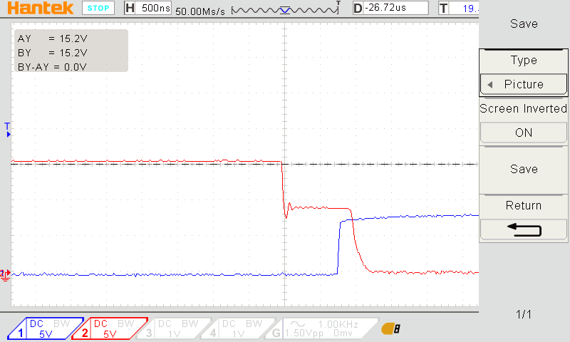
I explored waveforms for gate(MOSFET) of high- and low-side. You can see that MOSFET of high-side has stair. And there (eval1&eval3) has small time when exists short curcuit because low-side and high-side mosfet are opened simultaneously. That situation is not always. Approximately 50% of wafeforms. Correct wafeform is shown in "eval4".
How to fix it?
Thank you in advance.
Labels:
- Labels:
-
Motor Control Hardware
2 REPLIES 2
Options
- Mark as New
- Bookmark
- Subscribe
- Mute
- Subscribe to RSS Feed
- Permalink
- Email to a Friend
- Report Inappropriate Content
2020-06-26 10:21 AM
I made an oscillogram still.
Red-HSV (here you can see part of waveform that shouldn't)
Blue-LSV
LightBlue - SENSE2P(see the picture above)- in my case resistor=5mOhm
You can see that there that value is above 600mV.
I=600mV/5mOhm=120A
It means that there is short-circuit. High-side MOSFET is not closed when low-side MOSFET is opening. High-side MOSFET has parasitic value between high- and low-signal.
Options
- Mark as New
- Bookmark
- Subscribe
- Mute
- Subscribe to RSS Feed
- Permalink
- Email to a Friend
- Report Inappropriate Content
2020-07-28 08:09 AM
Hi @Shevtsov sorry for the late reply.
I have some questions to better understand your application behavior.
First of all the high side gate signal (HSx) must be referred to respective OUTx.
If you do not have a differential probe you can monitors both signal versus ground and show them (if a Math function of oscilloscope if available you can display 'HS - OUT' voltage).
From the scopes it seems you are supplying the board with VM = 8 V, could you confirm it?
How you are driving the device?
In particular in which way are you set the Advanced-control timer (TIM1) used to generate the PWM signal for the three half-bridge gate drivers and relative deadtimes?