Turn on suggestions
Auto-suggest helps you quickly narrow down your search results by suggesting possible matches as you type.
Showing results for
- STMicroelectronics Community
- STM32 MCUs
- STM32 MCUs Products
- TIM I2S using SPI
Options
- Subscribe to RSS Feed
- Mark Topic as New
- Mark Topic as Read
- Float this Topic for Current User
- Bookmark
- Subscribe
- Mute
- Printer Friendly Page
TIM I2S using SPI

Options
- Mark as New
- Bookmark
- Subscribe
- Mute
- Subscribe to RSS Feed
- Permalink
- Email to a Friend
- Report Inappropriate Content
2023-06-01 1:17 AM
Hello Everybody,
I am trying to emulate I2S using the SPI interface on the STM32F103.
I have looked at the AN5086, but setting up the timer correctly is still unsuccessful.
The SPI-CLK is connected to the TIM2 via Channel configured as "input capture direct mode".
The timer itself is clocked from "internal clock" source.
Channel 3 is configured as "output compare CH3".
What am I missing?
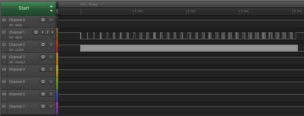
With a logic analyser I can the SPI transmitting. But no toggle from TIM2/CH3
The TIM2 is started in the code with: "HAL_TIM_Base_Start(&htim2);"
Please find attached the .ioc file
Kind regards,
pieterg!
This discussion is locked. Please start a new topic to ask your question.
5 REPLIES 5

Options
- Mark as New
- Bookmark
- Subscribe
- Mute
- Subscribe to RSS Feed
- Permalink
- Email to a Friend
- Report Inappropriate Content
2023-06-01 1:39 AM
What is the hardware and how exactly is it connected?
What are the expectations and what are the symptoms?
Read out and check/post content of TIM2 and relevant GPIO/AFIO registers.
JW
Options
- Mark as New
- Bookmark
- Subscribe
- Mute
- Subscribe to RSS Feed
- Permalink
- Email to a Friend
- Report Inappropriate Content
2023-06-01 4:28 AM
Hello Jan,
I am testing this with a STM32F103 "blue pill".
The hardware connections are simply:
The SPI-CLK (PB13) <-> TIM2 (PA1) on Channel 2 "Input Capture Direct Mode"
TIM2 CH3 "output compare" (PB10) <-> WS or LRCLK of I2S device
The desired effect is that, as far as I can understand, the TIM2 counts the SPI-SCK pulses and then "flips" TIM2 CH3 after 15 clocks.
Hope my explanation is clear enough.
Kind regards,
pieterg!
Options
- Mark as New
- Bookmark
- Subscribe
- Mute
- Subscribe to RSS Feed
- Permalink
- Email to a Friend
- Report Inappropriate Content
2023-06-01 5:15 AM
Read out and check/post content of TIM2 and relevant GPIO/AFIO registers.
JW
Options
- Mark as New
- Bookmark
- Subscribe
- Mute
- Subscribe to RSS Feed
- Permalink
- Email to a Friend
- Report Inappropriate Content
2023-06-01 6:29 AM - edited 2023-11-20 4:15 AM
Hello Jan,
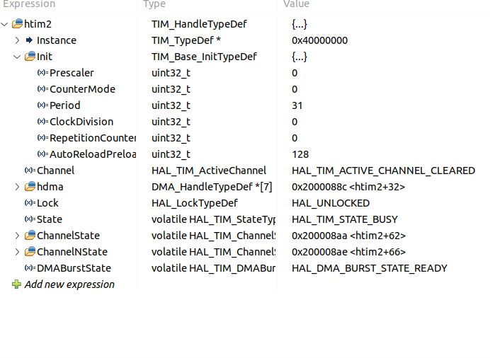
TIM2:

Options
- Mark as New
- Bookmark
- Subscribe
- Mute
- Subscribe to RSS Feed
- Permalink
- Email to a Friend
- Report Inappropriate Content
2023-06-01 6:58 AM
Have you had a look at those registers yourself, checking their content against the description in RM?
Decimal printouts or registers are not that useful. What's obvious at first sight is that TIM2_SMCR is zero, i.e. there's no slave-mode controller set, this timer runs out of its internal clock (it does count as witnessed by nonzero CNT, just not out of the external clock you expect). Also, TIM2_CCER is zero, i.e. TIM2_CH3 is disabled. You may want to check TIMx_CCMR2.OC3M too.
JW

Related Content
- Issues with STM32F4 USBX supporting both USB CDC and MSC in STM32 MCUs Embedded software
- Regarding the ADC settings for the EVSPIN32G4 in STM32 MCUs Boards and hardware tools
- STM32F303RE Comparator to Timer Channel Internal Mux Bug report with Workaround in STM32CubeMX (MCUs)
- STM32U5 - application with both normal and LPBAM I2C routine with LPDMA and GPDMA in STM32 MCUs Products
- STM32N6570-DK NonSecure Application not run. in STM32 MCUs Embedded software