Turn on suggestions
Auto-suggest helps you quickly narrow down your search results by suggesting possible matches as you type.
Showing results for
- STMicroelectronics Community
- STM32 MCUs
- STM32 MCUs Products
- Re: STM32L431 strange current draw
Options
- Subscribe to RSS Feed
- Mark Topic as New
- Mark Topic as Read
- Float this Topic for Current User
- Bookmark
- Subscribe
- Mute
- Printer Friendly Page
STM32L431 strange current draw
Options
- Mark as New
- Bookmark
- Subscribe
- Mute
- Subscribe to RSS Feed
- Permalink
- Email to a Friend
- Report Inappropriate Content
2023-04-08 01:43 AM - edited 2023-11-20 08:43 AM
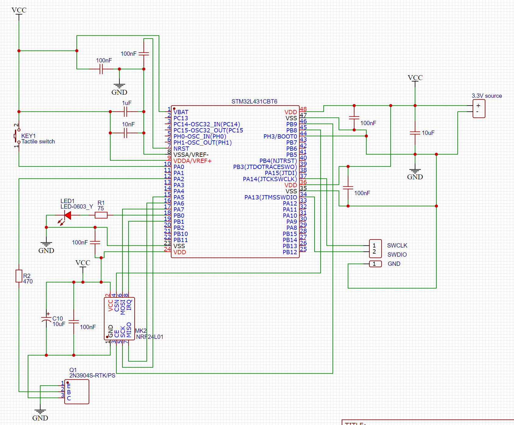
I have made a small/simple circuit with an STM32L431, where I first made a prototype version on a breadboard and then had the same circuit manufactured on a custom PCB:

The breadboard edition works exactly as expected. The PCB edition however is acting up.
I'm supplying power and measuring current with a Nordic semiconductor PPK2. Both MCUs have been programmed with the same program that goes into an endless loop.
This is what the current looks like in the breadboard prototype edition:

And PCB:

I can connect my stlink to the target just after powering it up, but once the current starts to spike I lose the connection.
I've measured the NRST pin with a scope and it seems to always be high.
Any ideas for what could cause this?
Labels:
- Labels:
-
STM32L4 Series
8 REPLIES 8
Options
- Mark as New
- Bookmark
- Subscribe
- Mute
- Subscribe to RSS Feed
- Permalink
- Email to a Friend
- Report Inappropriate Content
2023-04-08
06:03 AM
- last edited on
2023-12-06
04:43 AM
by
![]() Laurids_PETERSE
Laurids_PETERSE
...open cmos inputs...
try:

If you feel a post has answered your question, please click "Accept as Solution".
Options
- Mark as New
- Bookmark
- Subscribe
- Mute
- Subscribe to RSS Feed
- Permalink
- Email to a Friend
- Report Inappropriate Content
2023-04-08 03:02 PM
The circuit is a little bit strange:
- GND of MK2 NRF24L01 is switched with NPN transistor and floating then (behavior unknown)
- use CE for switch MK2 and add a pulldown resistor in this line from PB9 (for low level during startup)
- R1 is very low and therefore current from PB0 very high -> use driver for higher currents or low current LED with hiher resistor (2mA)
Options
- Mark as New
- Bookmark
- Subscribe
- Mute
- Subscribe to RSS Feed
- Permalink
- Email to a Friend
- Report Inappropriate Content
2023-04-08 11:44 PM
Does not seem to make any difference unfortunately.
Options
- Mark as New
- Bookmark
- Subscribe
- Mute
- Subscribe to RSS Feed
- Permalink
- Email to a Friend
- Report Inappropriate Content
2023-04-08 11:46 PM
Fair points, but I think there's something else wrong as I've currently only mounted the MCU and decoupling capacitors and I'm still seeing the same issue. I'm really at a loss, but I'm clearly doing something wrong. :grinning_face_with_sweat:
Options
- Mark as New
- Bookmark
- Subscribe
- Mute
- Subscribe to RSS Feed
- Permalink
- Email to a Friend
- Report Inappropriate Content
2023-04-09 12:00 AM
so make R1 470 r ; switch pullup or -down ON for all inputs (to NRF, switch etc.);
i see no ground-plane - is there on bottom side ??
btw
this kind of "noise" is typical for open/floating input or a bad contact/solder joint. control this again...
If you feel a post has answered your question, please click "Accept as Solution".
Options
- Mark as New
- Bookmark
- Subscribe
- Mute
- Subscribe to RSS Feed
- Permalink
- Email to a Friend
- Report Inappropriate Content
2023-04-09 05:57 AM
On the other side it's also strange that your breadboard is working at all without any decoupling capacitors etc. Are you sure that this is working correct or does it stay in a constant reset/sleep state (without any change in current consumption)?
For your custom PCB I would suppose a problem in routing, soldering or other hardware problem (e.g. damaged or fake MCU).
First seconds of your current diagram seems to be ok and constant.
Are there any peripherals initialized during startup? Please set a breakpoint to main entry point, step the initailization functions and monitor the current. There you can see if any peripheral causing problems (e.g. switch GPIO output to short circuit against GND or VDD).
Also observe if the MCU is heating up strongly...
Options
- Mark as New
- Bookmark
- Subscribe
- Mute
- Subscribe to RSS Feed
- Permalink
- Email to a Friend
- Report Inappropriate Content
2023-04-09 09:02 AM - edited 2023-11-20 08:43 AM
The breadboard MCU is decoupled same as the PCB, as close as I could get the capacitors to the MCU, they were just hidden on the other pic:

I think it sounds likely that it's the soldering. I think I will retry that tomorrow with fresh components.
Options
- Mark as New
- Bookmark
- Subscribe
- Mute
- Subscribe to RSS Feed
- Permalink
- Email to a Friend
- Report Inappropriate Content
2023-04-09 09:05 AM - edited 2023-11-20 08:43 AM
I tried carefully going over every solder joint under a microscope, cleaned with IPA and let it dry before powering it up again, but it seems I made it even more mad: 
Let me try with new components tomorrow and report back.
Related Content
- General Purpose Timer as Wakeup in STM32 MCUs Products
- RTC Timestamping Delay? in STM32 MCUs Embedded software
- Losing RTC ticks after wakeup timer in STM32 MCUs Embedded software
- Framing error generated after RS485 plugging and unplugging in STM32 MCUs Embedded software
- NUCLEO-WL33CC1 fails to connect after a succesfull programming in STM32 MCUs Wireless