Turn on suggestions
Auto-suggest helps you quickly narrow down your search results by suggesting possible matches as you type.
Showing results for
- STMicroelectronics Community
- STM32 MCUs
- STM32 MCUs Products
- Datasheet error and mismatch STM32H7B3I-DK for ARD...
Options
- Subscribe to RSS Feed
- Mark Topic as New
- Mark Topic as Read
- Float this Topic for Current User
- Bookmark
- Subscribe
- Mute
- Printer Friendly Page
Datasheet error and mismatch STM32H7B3I-DK for ARDUINO configurations URGENT
Options
- Mark as New
- Bookmark
- Subscribe
- Mute
- Subscribe to RSS Feed
- Permalink
- Email to a Friend
- Report Inappropriate Content
2020-10-22 11:21 AM
Hi Team
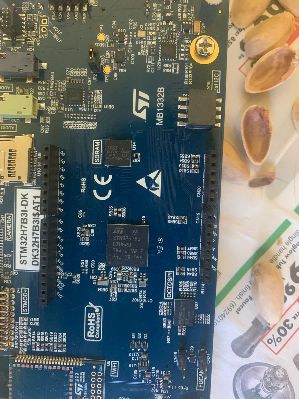
I am plannimng to connect the arduino and and STM32H7B3I-DK (MB1332B)
I see that in the document USART4_TX PH13 D1 and USART3_RX PB11 D0
I am getting confused how RX is on USART 3 and TX is on USART 4.
some thing which i am not able to get it right in the document
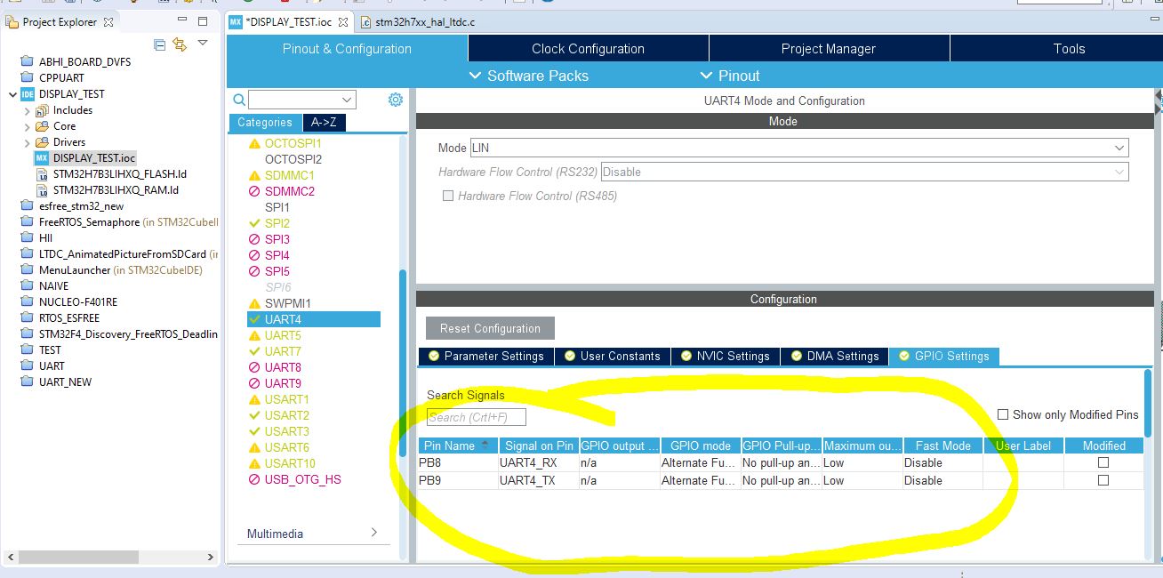
I have attached the images that shows the that UART TX4 and UART RX4 has the pin PH13 and PH14.
But when i tried to enable the code in the STM32IDE i see that the pins being used as
PB8 and PB9 for UART4
so how can i configure the UART pin in the code so i can use uart4 and receive the data
I have attached the images for references
can anyone please help me to get the right confiugration and point me to exact version of document and pin confiugrations
Thank you
Deepak R
Solved! Go to Solution.
Labels:
- Labels:
-
STM32H7 series
-
UART-USART
This discussion is locked. Please start a new topic to ask your question.
1 ACCEPTED SOLUTION
Accepted Solutions
Options
- Mark as New
- Bookmark
- Subscribe
- Mute
- Subscribe to RSS Feed
- Permalink
- Email to a Friend
- Report Inappropriate Content
2020-10-22 3:44 PM
How is it conceivably going to work with PB8/PB9?
You're going to have to drive the user interface to select PH13/PH14 and associate them with UART4. These aren't my tools.
I thought we'd already established that the VCP used USART1 on PA9/PA10
>>I did not undertand what do you mean by pin/change in chip level
These aren't my tools, my expectation is you have to click on the chip pin diagram to select the PH13 pins and associate them with UART4, similarly disassociate the PB8/PB9, which I have no idea why it fixated on for this board.
Tips, Buy me a coffee, or three.. PayPal Venmo
Up vote any posts that you find helpful, it shows what's working..
Up vote any posts that you find helpful, it shows what's working..
9 REPLIES 9
Options
- Mark as New
- Bookmark
- Subscribe
- Mute
- Subscribe to RSS Feed
- Permalink
- Email to a Friend
- Report Inappropriate Content
2020-10-22 11:44 AM
Team Of One Here,
Surely it is not that hard to figure out what's actually connected to what?
https://community.st.com/s/question/0D53W00000LdOOySAN/interfacing-stm32-and-arduino-uno-v3-shield
>>But when i tried to enable the code in the STM32IDE i see that the pins being used as PB8 and PB9 for UART4 so how can i configure the UART pin in the code so i can use uart4 and receive the data
That's presumably ONE choice for UART4, need to change at a pin/chip level
Tips, Buy me a coffee, or three.. PayPal Venmo
Up vote any posts that you find helpful, it shows what's working..
Up vote any posts that you find helpful, it shows what's working..
Options
- Mark as New
- Bookmark
- Subscribe
- Mute
- Subscribe to RSS Feed
- Permalink
- Email to a Friend
- Report Inappropriate Content
2020-10-22 1:53 PM
Options
- Mark as New
- Bookmark
- Subscribe
- Mute
- Subscribe to RSS Feed
- Permalink
- Email to a Friend
- Report Inappropriate Content
2020-10-22 1:53 PM
Options
- Mark as New
- Bookmark
- Subscribe
- Mute
- Subscribe to RSS Feed
- Permalink
- Email to a Friend
- Report Inappropriate Content
2020-10-22 2:01 PM
I'd be inclined to believe the schematic over the user's manual. Toggling the pin with GPIO and measuring should also provide your answer.
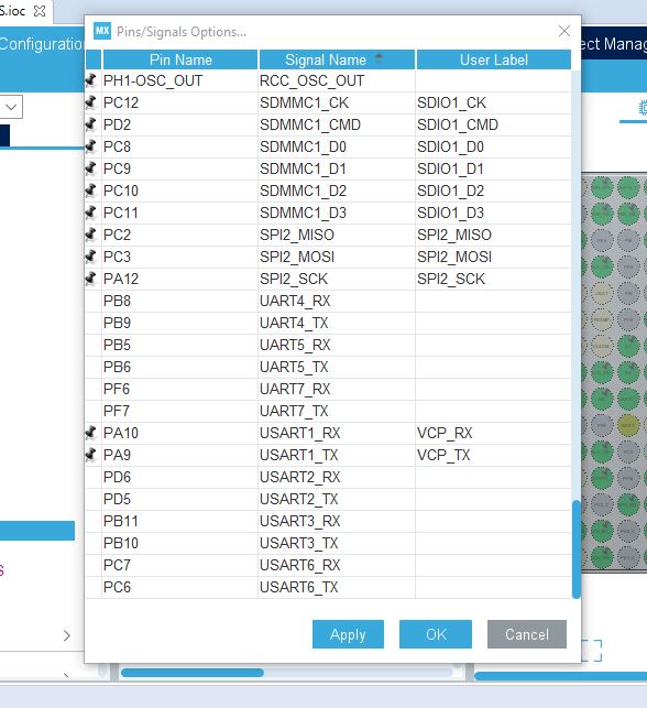
Change pins by selecting the pin you want in the pinout view and changing its function to what you want. In this case, select PH13 and set its mode to UART4_TX.
If you feel a post has answered your question, please click "Accept as Solution".
Options
- Mark as New
- Bookmark
- Subscribe
- Mute
- Subscribe to RSS Feed
- Permalink
- Email to a Friend
- Report Inappropriate Content
2020-10-22 2:26 PM
Ok, but I don't know how that advances the understanding on what's going on with the DK board
Tips, Buy me a coffee, or three.. PayPal Venmo
Up vote any posts that you find helpful, it shows what's working..
Up vote any posts that you find helpful, it shows what's working..
Options
- Mark as New
- Bookmark
- Subscribe
- Mute
- Subscribe to RSS Feed
- Permalink
- Email to a Friend
- Report Inappropriate Content
2020-10-22 3:14 PM
Hi clive
That's presumably ONE choice for UART4, need to change at a pin/chip level
I did not undertand what do you mean by pin/change in chip level
However i tried somethings I see that the following configurations as showed in the attachment
of VCPTX AND VCP RX will that anyway help me
I have 2 questions
1)Shall i believe that the code being generated is right
and there is a problem in the pins named in schematic and continue as PB8 and PB9 is the right pins
OR
2)Believing schematic is right .
Is there a way to change the pin names in the code to PH13 *** PH14 instead of PB8 and PB9 so it works
Thank you
Deepak R
Options
- Mark as New
- Bookmark
- Subscribe
- Mute
- Subscribe to RSS Feed
- Permalink
- Email to a Friend
- Report Inappropriate Content
2020-10-22 3:20 PM
Can you please let me know
what chnages are needed for Toggling the pin with GPIO and measuring should also provide your answer ?
Is it like just make the connections and try something ?? can you pleas eprovide information more
how can i change the pinout view I see that following configurations are there to ph13 ad PH14
Attached the pin configurations
Please help out
Options
- Mark as New
- Bookmark
- Subscribe
- Mute
- Subscribe to RSS Feed
- Permalink
- Email to a Friend
- Report Inappropriate Content
2020-10-22 3:44 PM
How is it conceivably going to work with PB8/PB9?
You're going to have to drive the user interface to select PH13/PH14 and associate them with UART4. These aren't my tools.
I thought we'd already established that the VCP used USART1 on PA9/PA10
>>I did not undertand what do you mean by pin/change in chip level
These aren't my tools, my expectation is you have to click on the chip pin diagram to select the PH13 pins and associate them with UART4, similarly disassociate the PB8/PB9, which I have no idea why it fixated on for this board.
Tips, Buy me a coffee, or three.. PayPal Venmo
Up vote any posts that you find helpful, it shows what's working..
Up vote any posts that you find helpful, it shows what's working..
Options
- Mark as New
- Bookmark
- Subscribe
- Mute
- Subscribe to RSS Feed
- Permalink
- Email to a Friend
- Report Inappropriate Content
2020-10-22 4:22 PM
Related Content
- Issue Interfacing with AP memory. in STM32 MCUs Products
- Issue with MIPI DSI Video Mode and SN65DSI83 Bridge on STM32H747 in Others: STM32 MCUs related
- STM32U5 USB Interrupt Based Approach in STM32 MCUs Embedded software
- STSPIN32G4 Internal LDO Outputting 4.1V Instead of 3.3V - Configuration Issue in STM32 MCUs Motor control
- Parameter configuration for High Speed BLDC Motor in STM32 MCUs Motor control