Turn on suggestions
Auto-suggest helps you quickly narrow down your search results by suggesting possible matches as you type.
Showing results for
- STMicroelectronics Community
- STM32 MCUs
- STM32 MCUs Products
- INTERFACING STM32 AND ARDUINO UNO V3 SHIELD
Options
- Subscribe to RSS Feed
- Mark Topic as New
- Mark Topic as Read
- Float this Topic for Current User
- Bookmark
- Subscribe
- Mute
- Printer Friendly Page
INTERFACING STM32 AND ARDUINO UNO V3 SHIELD
Options
- Mark as New
- Bookmark
- Subscribe
- Mute
- Subscribe to RSS Feed
- Permalink
- Email to a Friend
- Report Inappropriate Content
2020-10-22 8:33 AM
Hi Team
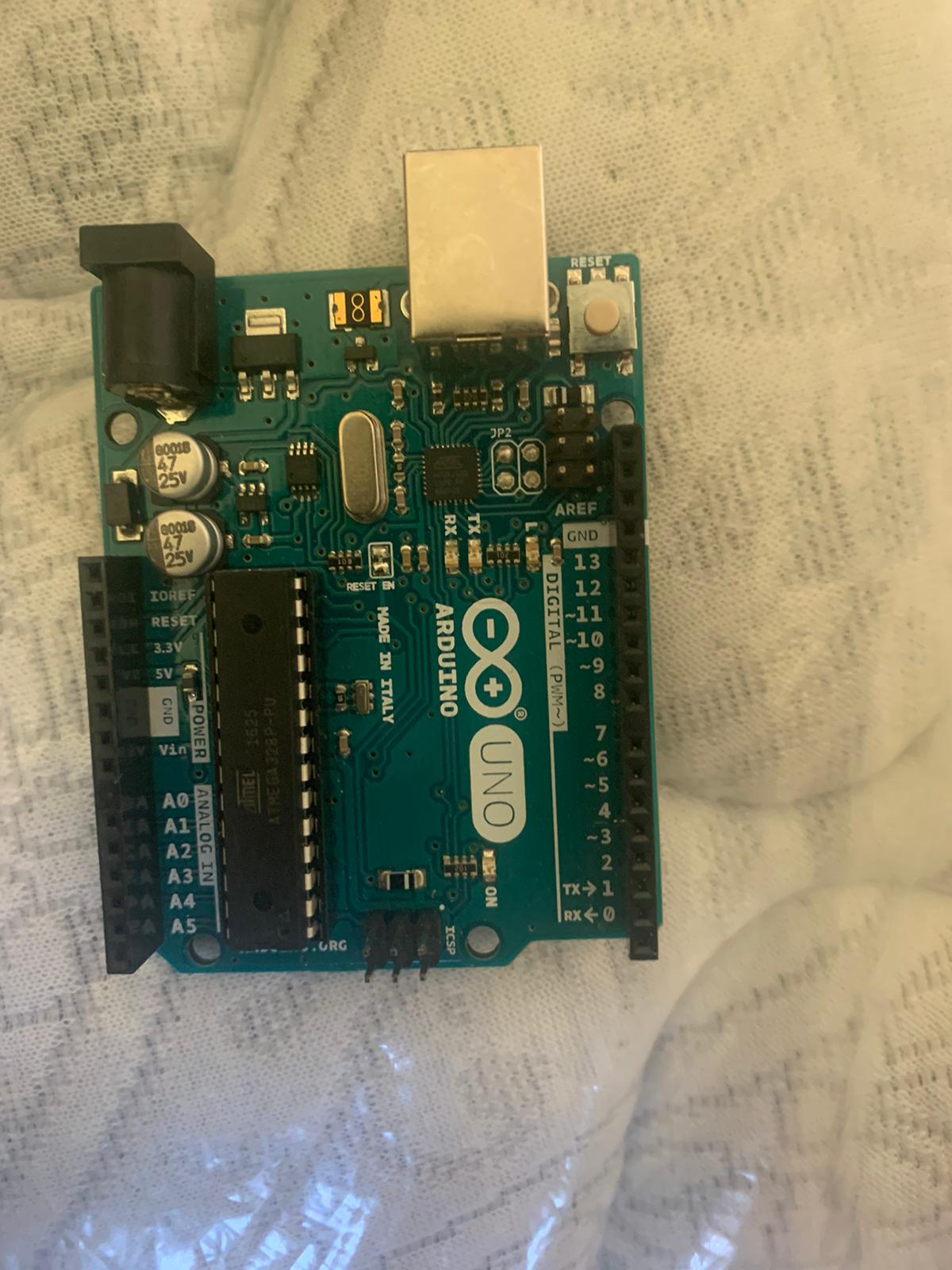
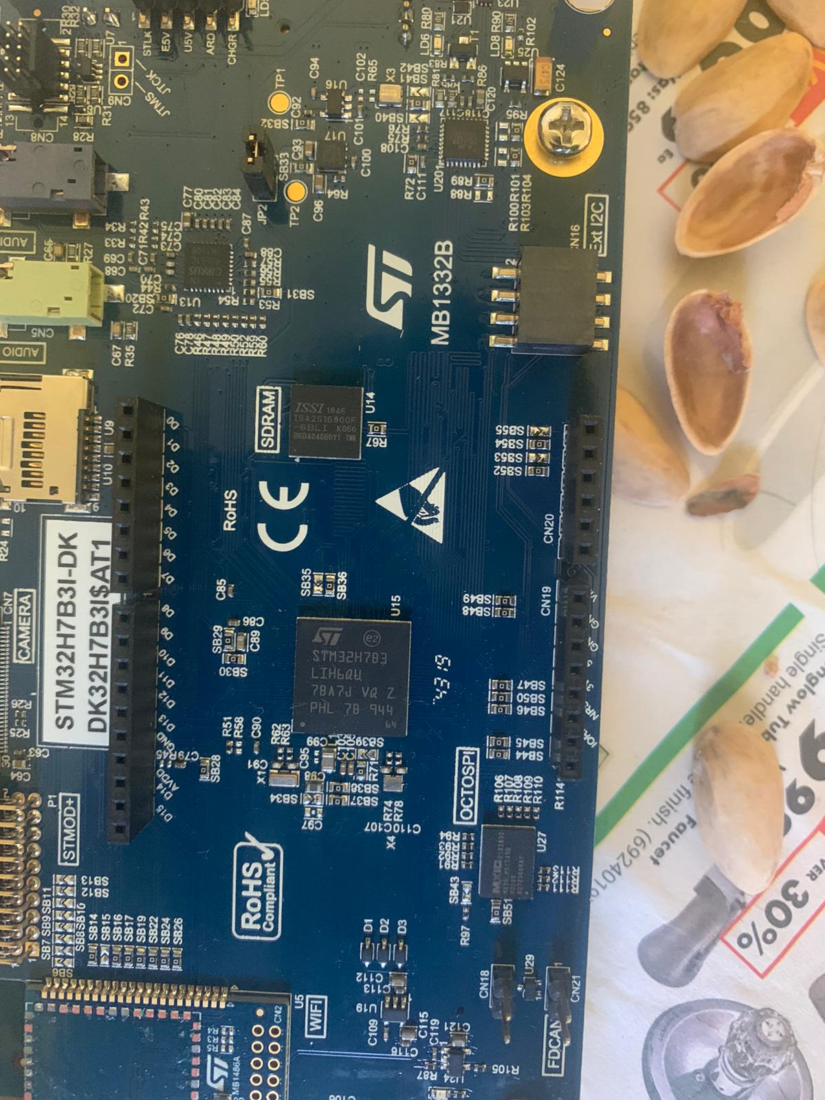
I am trying to interface ARDUINO ans STM32H7B31 I have both boards and i have studied the document that says the arduino connections CN10 CN11 CN19 CN20
I hope it need and interface/shield to to connect as both the boards have the female connectors and not bale to fix it I have ARDUINO V3 board
Can you please help me on getting the exact shield that is needed for connecting these boards
I have attached both the images Can you please help on fixing both .
Thank you
Deepak R
Labels:
- Labels:
-
STM32H7 series
This discussion is locked. Please start a new topic to ask your question.
7 REPLIES 7
Options
- Mark as New
- Bookmark
- Subscribe
- Mute
- Subscribe to RSS Feed
- Permalink
- Email to a Friend
- Report Inappropriate Content
2020-10-22 9:09 AM
The STM32H7B3I-DK is designed to host shields, not the Arduino itself.
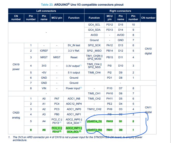
You can cross connect the Serial ports via D0/D1 pins on the headers, and providing a common ground.
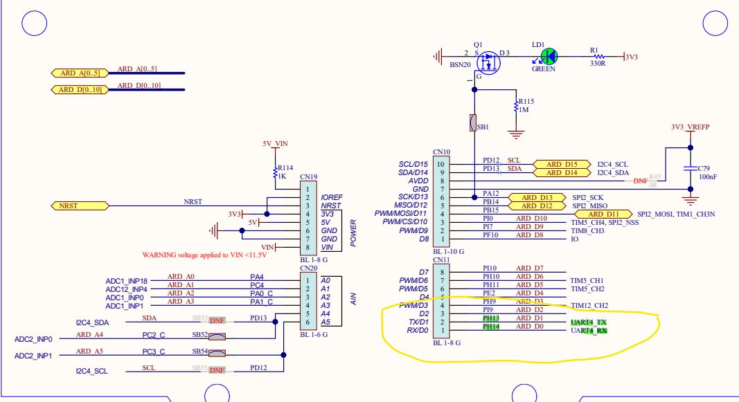
On the STM32H7B3I-DK (REV B) the D1 pin is the OUTPUT UART4_TX, D0 is the INPUT UART4_RX
Tips, Buy me a coffee, or three.. PayPal Venmo
Up vote any posts that you find helpful, it shows what's working..
Up vote any posts that you find helpful, it shows what's working..
Options
- Mark as New
- Bookmark
- Subscribe
- Mute
- Subscribe to RSS Feed
- Permalink
- Email to a Friend
- Report Inappropriate Content
2020-10-22 11:02 AM
Hi Clive
Thanks for providing the feedback
I will connect the common ground on arduino and and STM32H7B3I-DK and also connect the UART TX and RX PIN Thnaks for helping and correcting me .
I see that in the document USART4_TX PH13 D1 and USART3_RX PB11 D0
I am getting confused how RX is on USART 3 and TX is on USART 4.
some thing which i am not able to get it right in the document
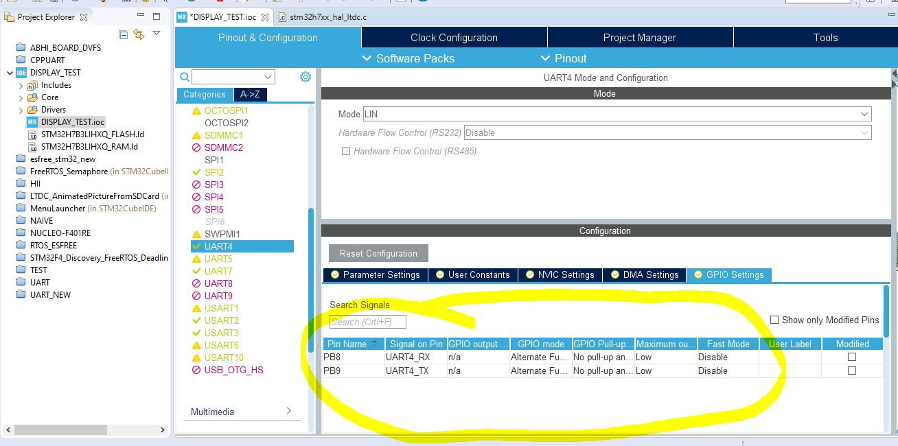
I have attached the images that shows the that UART TX4 and UART RX4 has the pin PH13 and PH14 as you mentioned
But when i tried to enable the code in the STM32IDE i see that the pins being used for UART4 RX and UART4 TX are
PB8 and PB9
so how can i configure the UART pin in the code so i can use uart4 and receive the data and all configurations are in place
I have attached the images for references
Thank you
Deepak R
Options
- Mark as New
- Bookmark
- Subscribe
- Mute
- Subscribe to RSS Feed
- Permalink
- Email to a Friend
- Report Inappropriate Content
2020-10-22 11:02 AM
Options
- Mark as New
- Bookmark
- Subscribe
- Mute
- Subscribe to RSS Feed
- Permalink
- Email to a Friend
- Report Inappropriate Content
2020-10-22 11:02 AM
Options
- Mark as New
- Bookmark
- Subscribe
- Mute
- Subscribe to RSS Feed
- Permalink
- Email to a Friend
- Report Inappropriate Content
2020-10-22 11:03 AM
Options
- Mark as New
- Bookmark
- Subscribe
- Mute
- Subscribe to RSS Feed
- Permalink
- Email to a Friend
- Report Inappropriate Content
2020-10-22 11:09 AM
I'm going by the Rev B board schematics which should match your board.
This is not a board I have, so can't speak to the reality on the ground.
I'd start by trusting the schematic, and perhaps toggle the pins as GPIO and scoping them. Then you'd know for sure.
Tips, Buy me a coffee, or three.. PayPal Venmo
Up vote any posts that you find helpful, it shows what's working..
Up vote any posts that you find helpful, it shows what's working..
Options
- Mark as New
- Bookmark
- Subscribe
- Mute
- Subscribe to RSS Feed
- Permalink
- Email to a Friend
- Report Inappropriate Content
2020-10-22 11:18 AM
Thanks for the reply i will just connect the pins and see whether with default UART4 configurations works
Related Content
- Ardunio GIGA R1 - STM32H747I - cubeMX configuration- fail to power on in STM32 MCUs Boards and hardware tools
- External voltage reference on Nucleo-F072RB in STM32 MCUs Boards and hardware tools
- Multi protocol communication shield (Nucleo ZIO & Arduino Uno V3 compatible) in Others: STM32 MCUs related
- Nucleo-U545RE-Q Host Binaries for Flashing X‑NUCLEO‑67W61M1 (Mission Profile T01) in Others: STM32 MCUs related
- STM32 NUCLEO-F446RE + SmartElex ACS37800 (I2C) – Request for Reference / Sample Code in Others: STM32 MCUs related