Turn on suggestions
Auto-suggest helps you quickly narrow down your search results by suggesting possible matches as you type.
Showing results for
- STMicroelectronics Community
- STM32 MCUs
- STM32 MCUs Motor control
- How to supply independent VM and VBUS to STEVAL-SP...
Options
- Subscribe to RSS Feed
- Mark Topic as New
- Mark Topic as Read
- Float this Topic for Current User
- Bookmark
- Subscribe
- Mute
- Printer Friendly Page
How to supply independent VM and VBUS to STEVAL-SPIN3201 (STSPIN32F0)?
Options
- Mark as New
- Bookmark
- Subscribe
- Mute
- Subscribe to RSS Feed
- Permalink
- Email to a Friend
- Report Inappropriate Content
2021-07-09 12:20 PM
Hello,
I have a 48V motor and would like to evaluate this design using the STEVAL-SPIN3201 which is only rated to 45V.
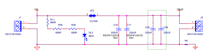
The schematic sort of suggests that if you remove the JP2 jumper you can independently supply VM and VBUS, and VBUS can go to 60 volts due to FET's limit and VM can go to 45V.
I removed this jumper and connected 48V to J2 for VBUS, and 24V to J1 for VM.
Changed the FW so I don't get overvoltage error and the SPIN32F0 programmed fine. But as soon as I commanded the motor to run the board burned out, appears to have burned at the VM input of the SPIN32F0.
Has anyone successfully provided separate VM and VBUS with this EVAL board?
Because I am just barely over the rated voltage, and the absolute maximum rating of the SPIN32F0 is actually 48V, I doubt the board burned up because the higher voltage, I suspect the 2 supplies are fighting each other somehow and I did not make all the changes to the board I needed to.
I had previously run this motor with this board at 42V fine, so I don't believe there is any FW issue here.
Thanks!
Solved! Go to Solution.
Labels:
1 ACCEPTED SOLUTION
Accepted Solutions
Options
- Mark as New
- Bookmark
- Subscribe
- Mute
- Subscribe to RSS Feed
- Permalink
- Email to a Friend
- Report Inappropriate Content
2021-07-20 01:22 AM
Hi @Community member,
when I mentioned the Absolute Maximum Ratings (AMR) of the device I was referring not only to the VM but also to the other gate driver parameters:
bootstrap voltage (VBOOT) and output voltage (VOUT).
When you turn-on the high-side MOS the OUT pin, and so the BOOT pin, is connected to the VBUS voltage (less than voltage drop on the MOS). As you may read, the AMR of OUT pin is dependent on VM value.
For this reason you cannot use two different supply voltage for VM and VBUS.
Let me know if I answered to your original question, if so please "Select as Best" button in the proper reply.
If you feel a post has answered your question, please click "Accept as Solution"
12 REPLIES 12
Options
- Mark as New
- Bookmark
- Subscribe
- Mute
- Subscribe to RSS Feed
- Permalink
- Email to a Friend
- Report Inappropriate Content
2021-07-11 08:13 PM
Dear @Community member
Welcome to the STM32 Community
Could you give more details to the STM32 Community about your setup?
That is to say the material you use (HW and also SW): CPU(s), board(s), motor(s), tools and versions, and so on.
And more especially did you use STM32 MC tools and what version of those tools you use (such as MC_suite, STM32 MC Motor Profile, STM32 MC SDK, STM32 MC Workbench, the used example, the origin of the base of your application source code, and so on)?
Please do not forget to also indicate the compilation tools suite you use (with the version number).
Best regards
Options
- Mark as New
- Bookmark
- Subscribe
- Mute
- Subscribe to RSS Feed
- Permalink
- Email to a Friend
- Report Inappropriate Content
2021-07-12 09:16 AM
Hi Laurent,
Thank you for the response. I used the following:
- ST Motor Profiler 5.Y.1
- ST Motor Control Workbench 5.Y.1.21203
- STM32CubeMX 6.2.1
- Firmware Package 1.11.2
- STM32CubeIDE 1.4.0
The board I am using is the STEVAL-SPIN3201. The motor is a 400W PMDC motor with 4 pole pairs, rated to 6000RPM and 48VDC.
I have used the SPIN3201 with this setup with a 42V supply, and it all works fine. In this experiment the only change I made was to remove the 0 ohm jumper JP2, provide a VM voltage at J1 of 24V, and a VBUS voltage at J2 of 48V.
Like I mentioned before, the datasheet for this eval board sort of suggests this can be done, but it does not explicitly say different voltages can be supplied for VM and VBUS.
Thanks,
-Kyler
Options
- Mark as New
- Bookmark
- Subscribe
- Mute
- Subscribe to RSS Feed
- Permalink
- Email to a Friend
- Report Inappropriate Content
2021-07-13 02:08 AM
Hi @Community member,
the STEVAL-SPIN3201 data brief and user manual state that the maximum rating for input supply voltage is from 8 V to 45 V.
In your case, applying the 48V to VBUS, you have violate the absolute maximum rating of STSPIN32F0 gate driver (refer to Table 1 in IC datasheet).
It's required to use the same supply voltage for VBUS and VM to avoid to violate the Absolute Maximum Ratings of the device.
The use of JP2 solder bridge may seem misleading, but its purpose is to monitor device and power stage consumption separately.
I hope these info are useful to you.
If you feel a post has answered your question, please click "Accept as Solution"
Options
- Mark as New
- Bookmark
- Subscribe
- Mute
- Subscribe to RSS Feed
- Permalink
- Email to a Friend
- Report Inappropriate Content
2021-07-13 07:29 AM
Hi,
The problem is the VM value never was more than 24 Volts, and it is, according data sheet "Table-1" is lower than 48 Volts. The Community member @KConn.2 said he power the IC with 24 Volts. By another hand, I see the only shared electrical connection between the STSPIN32F0 and the higher voltage of 48 Volts applied to VBUS (without the JP2 solder jumper) through the circuit network monitoring the VBUS Voltage. In that you have two divider voltage resistors of 169K and 9.3K, i.e., there is around 0.27 mA (for 48V in VBUS) producing 2.50 Volts at the input of voltage monitoring ADC pin; also you have a diode clamp to 3.3Volts in that monitoring circuit. Then, from where, the 48Volts applied to the Power Stage, are connecting with the 24 Volts applied to VM pin in the STSPIN32F0?
Regards.
Options
- Mark as New
- Bookmark
- Subscribe
- Mute
- Subscribe to RSS Feed
- Permalink
- Email to a Friend
- Report Inappropriate Content
2021-07-13 08:44 AM
Hi Cristiana, @Cristiana SCARAMEL
Thank you for the reply.
Yes I understand that the STSPIN32F0 cannot take more than 45VDC, and looking at the STEVAL schematic I thought I could provide 2 different voltages to allow for higher motor voltage without violating the STSPIN32F0 limits.
You say the jumper JP2 is only for enabling/disabling monitoring, but there appears to be 2 separate connectors for independent power to the board, J1 and J2, so it really seams like I am supposed to be able to provide independent voltages for the motor FET circuit and the gate driver circuit. If I search the schematic for VBUS I don't see anywhere where that net goes back to the F0.
Are you sure independent supplies cannot be provided, even if neither is above the 45V threshold. Say, what if I wanted to provide 24VDC to VM and 36VDC to VBUS?
Thank you,
-Kyler
Options
- Mark as New
- Bookmark
- Subscribe
- Mute
- Subscribe to RSS Feed
- Permalink
- Email to a Friend
- Report Inappropriate Content
2021-07-20 01:22 AM
Hi @Community member,
when I mentioned the Absolute Maximum Ratings (AMR) of the device I was referring not only to the VM but also to the other gate driver parameters:
bootstrap voltage (VBOOT) and output voltage (VOUT).
When you turn-on the high-side MOS the OUT pin, and so the BOOT pin, is connected to the VBUS voltage (less than voltage drop on the MOS). As you may read, the AMR of OUT pin is dependent on VM value.
For this reason you cannot use two different supply voltage for VM and VBUS.
Let me know if I answered to your original question, if so please "Select as Best" button in the proper reply.
If you feel a post has answered your question, please click "Accept as Solution"
Options
- Mark as New
- Bookmark
- Subscribe
- Mute
- Subscribe to RSS Feed
- Permalink
- Email to a Friend
- Report Inappropriate Content
2021-07-20 02:09 AM
Hi @MM.22arcoccia and welcome to the ST Community.
As you can read in my just below reply, when you turn-on the high-side MOS the OUT pin, and so the BOOT pin, is connected to the VBUS voltage (less than voltage drop on the MOS).
As you may read in the Table 1 datasheet, the AMR of OUT pin is dependent on VM value.
So if you use a VBUS voltage of 48 V using VM = 24 V you are violating the AMR of OUT pin.
If you feel a post has answered your question, please click "Accept as Solution"
Options
- Mark as New
- Bookmark
- Subscribe
- Mute
- Subscribe to RSS Feed
- Permalink
- Email to a Friend
- Report Inappropriate Content
2021-07-20 09:09 AM
Hi Christiana, yes this sounds like the same explanation that one of our EE's gave as well. The gate and drain voltages on the FET's will not operate independently, the SPIN32F0 will try to boost the gate voltage over the drain voltage and that's probably how my chip burned out.
@Cristiana SCARAMEL we will probably be moving forward with our own design now, based on the STM32F446RE, but use a higher voltage gate driver (maybe a TI DRV8301) and some higher power FETs. Do you know if ST has a reference design for a 60V, ~20A FOC controller, ideally based around the F446RE since we are happy with its functionality when using the NUCLEO-446RE + IHM07M1, just need higher voltage/current capability
Thank you,
-Kyler
Options
- Mark as New
- Bookmark
- Subscribe
- Mute
- Subscribe to RSS Feed
- Permalink
- Email to a Friend
- Report Inappropriate Content
2021-07-21 06:59 AM
Hi @Community member,
I can suggest you the STDRIVE101 Triple half-bridge gate driver (operating range up to 75 V).
You can evaluate the device performance with the EVALSTDRIVE101 demonstration board and NUCLEO-F446RE adding the X-NUCLEO-IHM09 connector adapter.
Moreover, these boards are supported by the STM32 Motor Control Software Development Kit Rev Y X-CUBE-MCSDK-Y (download the Rev Y).
Otherwise, if you want to consider a System-In-Package solution we have the high voltage IC integrating the same MCU of STPIN32F0:
Good work!
If you feel a post has answered your question, please click "Accept as Solution"