Turn on suggestions
Auto-suggest helps you quickly narrow down your search results by suggesting possible matches as you type.
Showing results for
- STMicroelectronics Community
- STM32 MCUs
- STM32 MCUs Boards and hardware tools
- STM32F103C8 production board schematic
Options
- Subscribe to RSS Feed
- Mark Topic as New
- Mark Topic as Read
- Float this Topic for Current User
- Bookmark
- Subscribe
- Mute
- Printer Friendly Page
STM32F103C8 production board schematic
Options
- Mark as New
- Bookmark
- Subscribe
- Mute
- Subscribe to RSS Feed
- Permalink
- Email to a Friend
- Report Inappropriate Content
2022-01-14 2:47 AM
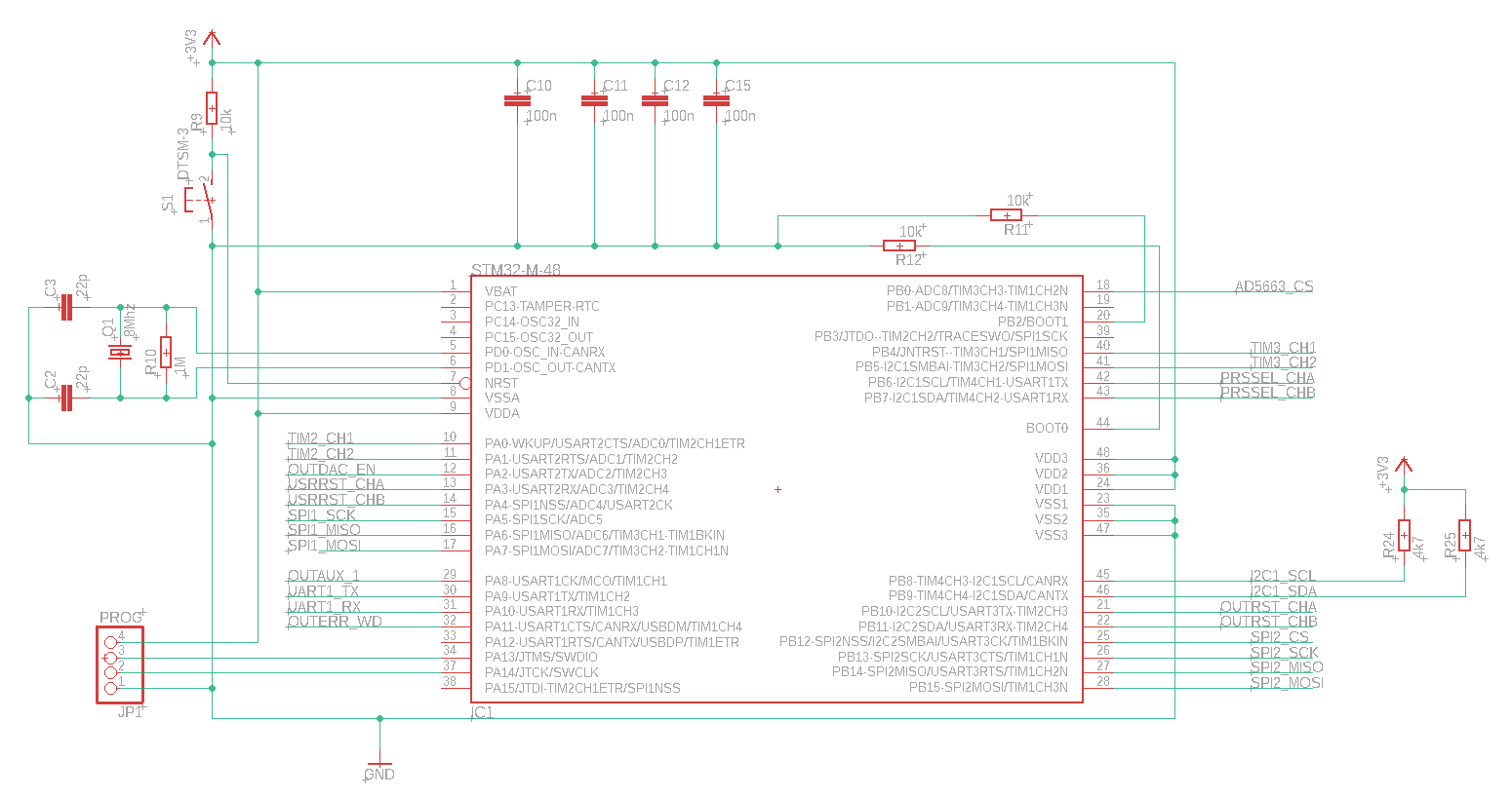
I'm working on a board design with a STM32F103C8. First time for me to build a PCB with STM32, I've always worked with "blue pill" boards.
Not sure about BOOT wiring. The firmware will be uploaded using STM32CubeProgrammer. The board should startup using the internal firmware.
Only HSE External Crystal is used, 8Mhz.
PROG connect is used for programming/debugging.
Can you confirm this design will work? Thanks!
Note: first post here, so excuse me if I'm doing wrong.
Solved! Go to Solution.
Labels:
- Labels:
-
STM32F1 Series
This discussion is locked. Please start a new topic to ask your question.
15 REPLIES 15
Options
- Mark as New
- Bookmark
- Subscribe
- Mute
- Subscribe to RSS Feed
- Permalink
- Email to a Friend
- Report Inappropriate Content
2022-01-14 6:35 AM
Options
- Mark as New
- Bookmark
- Subscribe
- Mute
- Subscribe to RSS Feed
- Permalink
- Email to a Friend
- Report Inappropriate Content
2022-01-14 6:36 AM
Done below
Options
- Mark as New
- Bookmark
- Subscribe
- Mute
- Subscribe to RSS Feed
- Permalink
- Email to a Friend
- Report Inappropriate Content
2022-01-14 6:36 AM
Now it looks ok.
Regards
/Peter
In order to give better visibility on the answered topics, please click on Accept as Solution on the reply which solved your issue or answered your question.
Options
- Mark as New
- Bookmark
- Subscribe
- Mute
- Subscribe to RSS Feed
- Permalink
- Email to a Friend
- Report Inappropriate Content
2022-01-15 9:57 AM
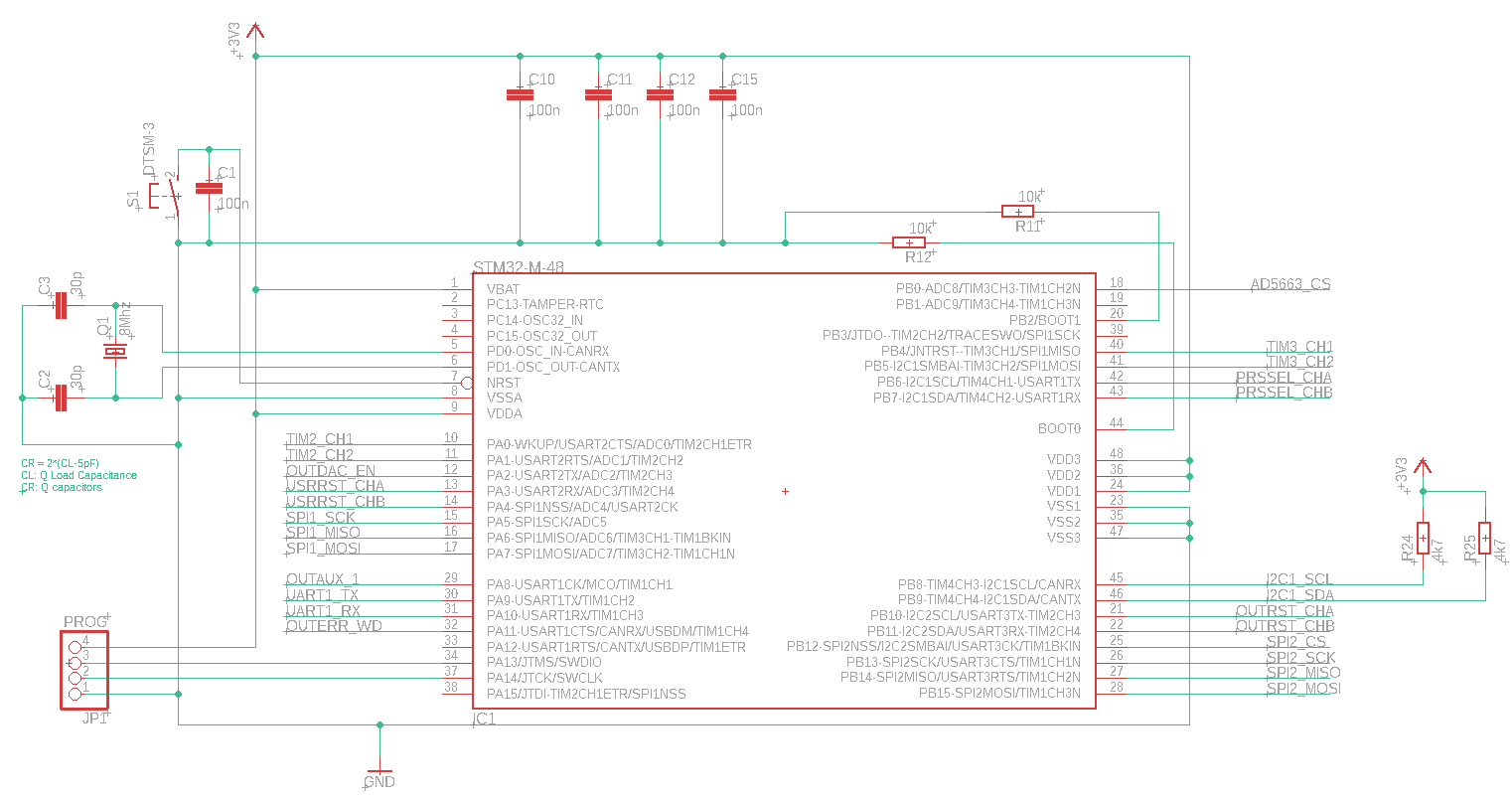
Take a note that on 2 layer boards the stray capacitance is significantly smaller than on 4 or more layer boards. My experience says that on 2 layer boards with short routes to crystal the Cs is typically only 1-2 pF.
We measured such a board with a crystal CL = 12 pF and tried a few capacitor values. Here are the resulting LSE frequency offsets relative to an external precision reference clock:
15 pF:  +25 ppm
18 pF:  +15 ppm
22 pF: +1,6 ppm
Indirectly it shows that a stray capacitance should be Cs = (2 * 12 pF - 22 pF) / 2 = 1 pF.
Options
- Mark as New
- Bookmark
- Subscribe
- Mute
- Subscribe to RSS Feed
- Permalink
- Email to a Friend
- Report Inappropriate Content
2022-01-16 11:52 PM
Thanks! Indeed I'm using a 2 layer board.
Options
- Mark as New
- Bookmark
- Subscribe
- Mute
- Subscribe to RSS Feed
- Permalink
- Email to a Friend
- Report Inappropriate Content
2022-03-01 6:12 AM
Quick update: design is loaded on PCB, I confirm it's working.
- « Previous
-
- 1
- 2
- Next »
Related Content
- Is it safe to reuse USB D+/D- (PA11/PA12) as GPIO after one-time DFU programming? in STM32 MCUs Products
- NUCLEO-N657 schematic discrepancy vs AN5967 regarding VDDA18PMU / VDDSMPS in STM32 MCUs Boards and hardware tools
- Request for STM32H745IIT6 Reference Design in STM32 MCUs Boards and hardware tools
- Can I use the STM32L433RCT6P without the external SMPS ? in STM32 MCUs Products
- STM32H735G-DK AZURE IOT THREADX in STM32 MCUs Embedded software