Turn on suggestions
Auto-suggest helps you quickly narrow down your search results by suggesting possible matches as you type.
Showing results for
- STMicroelectronics Community
- STM32 MCUs
- STM32 MCUs Boards and hardware tools
- Re: STM32F103C8 production board schematic
Options
- Subscribe to RSS Feed
- Mark Topic as New
- Mark Topic as Read
- Float this Topic for Current User
- Bookmark
- Subscribe
- Mute
- Printer Friendly Page
STM32F103C8 production board schematic
Options
- Mark as New
- Bookmark
- Subscribe
- Mute
- Subscribe to RSS Feed
- Permalink
- Email to a Friend
- Report Inappropriate Content
2022-01-14 2:47 AM
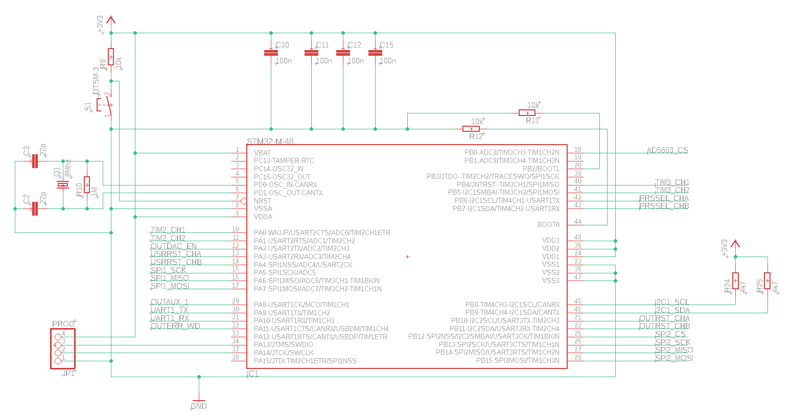
I'm working on a board design with a STM32F103C8. First time for me to build a PCB with STM32, I've always worked with "blue pill" boards.
Not sure about BOOT wiring. The firmware will be uploaded using STM32CubeProgrammer. The board should startup using the internal firmware.
Only HSE External Crystal is used, 8Mhz.
PROG connect is used for programming/debugging.
Can you confirm this design will work? Thanks!
Note: first post here, so excuse me if I'm doing wrong.
Solved! Go to Solution.
Labels:
- Labels:
-
STM32F1 Series
1 ACCEPTED SOLUTION
Accepted Solutions
Options
- Mark as New
- Bookmark
- Subscribe
- Mute
- Subscribe to RSS Feed
- Permalink
- Email to a Friend
- Report Inappropriate Content
2022-01-14 6:35 AM
15 REPLIES 15
Options
- Mark as New
- Bookmark
- Subscribe
- Mute
- Subscribe to RSS Feed
- Permalink
- Email to a Friend
- Report Inappropriate Content
2022-01-14 3:41 AM
Welcome, @Davide G_Oironi, to the community!
- C2, C3 seems to be a bit large, check AN2867 for correct values for your crystal
- R10 should not be necessary
- add a 100nF capacitor between NRST and GND
- R9 is also not required
Good luck!
Regards
/Peter
In order to give better visibility on the answered topics, please click on Accept as Solution on the reply which solved your issue or answered your question.
Options
- Mark as New
- Bookmark
- Subscribe
- Mute
- Subscribe to RSS Feed
- Permalink
- Email to a Friend
- Report Inappropriate Content
2022-01-14 5:58 AM
You should have a bulk 4.7uF capacitor on VDD somewhere.
Don't be afraid to use multiple GND and +3V3 symbols on your schematic to increase readability.
If you feel a post has answered your question, please click "Accept as Solution".
Options
- Mark as New
- Bookmark
- Subscribe
- Mute
- Subscribe to RSS Feed
- Permalink
- Email to a Friend
- Report Inappropriate Content
2022-01-14 6:06 AM
Thank you
@Peter BENSCH
1)
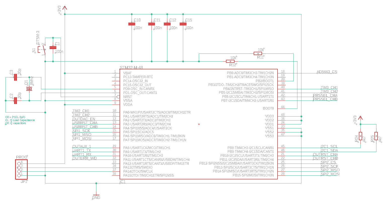
According to AN2867 if I'm right I should apply the 3.3 Load Capacitance formula
Supposing Cs 5pF, which I think is a common value for "standard" PCB, my oscillator should have by datasheet 20pF Load Capacitance, so (Cl1*Cl2)/(Cl1+Cl2)=20pF-5pF and Cl1==Cl2 => Cl1,Cl2=30pF
Does it sound right?
2)
Thank's to you I've look at the datasheet, the NRST already has a RPU resistor, so R9 could be removed
3)
done
4)
I've fond R10 in other schematics, never seen that on my AVR experience, I've to investigate why others (in blue pill for example) use this resistor
@TDK
Yes, I've a 10uF on the supply sheet.
You are right, readability is not that much with that few VDD and GND points.
Find schematic updated attached
Options
- Mark as New
- Bookmark
- Subscribe
- Mute
- Subscribe to RSS Feed
- Permalink
- Email to a Friend
- Report Inappropriate Content
2022-01-14 6:15 AM
The feeback resistor was used in the last century in oscillator circuits that did not have an internal one. However, the STM32s have had this feedback resistor built in since the STM32s era began in 2007.
Why it was used in the Blue Pill... only its developers know.
In order to give better visibility on the answered topics, please click on Accept as Solution on the reply which solved your issue or answered your question.
Options
- Mark as New
- Bookmark
- Subscribe
- Mute
- Subscribe to RSS Feed
- Permalink
- Email to a Friend
- Report Inappropriate Content
2022-01-14 6:17 AM
only its developers know :face_with_tears_of_joy: that's right :)
Thank you again.
About the 1) formula, is that right for a 20pF Load Capacitance? By the way the oscillator is a Fundamental one like specified in the AN2867 paper.
Options
- Mark as New
- Bookmark
- Subscribe
- Mute
- Subscribe to RSS Feed
- Permalink
- Email to a Friend
- Report Inappropriate Content
2022-01-14 6:20 AM
1: yes, 30pF sounds reasonable if CL is actually 20pF (didn't expect a crystal with such a huge load capacitance). 4..5pF for CS are quite common values.
Good luck!
/Peter
In order to give better visibility on the answered topics, please click on Accept as Solution on the reply which solved your issue or answered your question.
Options
- Mark as New
- Bookmark
- Subscribe
- Mute
- Subscribe to RSS Feed
- Permalink
- Email to a Friend
- Report Inappropriate Content
2022-01-14 6:29 AM
Options
- Mark as New
- Bookmark
- Subscribe
- Mute
- Subscribe to RSS Feed
- Permalink
- Email to a Friend
- Report Inappropriate Content
2022-01-14 6:30 AM
Thank you!
I've posted the updated schematic just in case, for other people.
Options
- Mark as New
- Bookmark
- Subscribe
- Mute
- Subscribe to RSS Feed
- Permalink
- Email to a Friend
- Report Inappropriate Content
2022-01-14 6:31 AM
Please open the shortcut from NRST to VDD.
In order to give better visibility on the answered topics, please click on Accept as Solution on the reply which solved your issue or answered your question.
Related Content
- Writing a program that updates itself at runtime in STM32 MCUs Products
- STM32F103 LSE load capacitance calculations (RTC) in STM32 MCUs Products
- I2C lines short with GND in STM32H745XIH6 in STM32 MCUs Products
- NUCLEO-L432KC - External power 3v3 in STM32 MCUs Boards and hardware tools
- How to support debugging and firmware upgrades on production boards in STM32 MCUs Products