Turn on suggestions
Auto-suggest helps you quickly narrow down your search results by suggesting possible matches as you type.
Showing results for
- STMicroelectronics Community
- STM32 MCUs
- STM32 MCUs Boards and hardware tools
- STM32F030C8T6 internal protection of port PB8 and ...
Options
- Subscribe to RSS Feed
- Mark Topic as New
- Mark Topic as Read
- Float this Topic for Current User
- Bookmark
- Subscribe
- Mute
- Printer Friendly Page
STM32F030C8T6 internal protection of port PB8 and PB9 (FTf ports): Is voltage -0.35V with 100k series resistor a problem for the STM32?
Options
- Mark as New
- Bookmark
- Subscribe
- Mute
- Subscribe to RSS Feed
- Permalink
- Email to a Friend
- Report Inappropriate Content
2020-04-29 01:24 AM
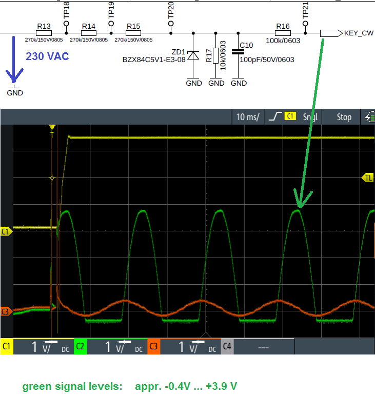
We use the schematic attached to convert a 230 VAC signal to the STM32 level (low cost product). Maximum input high level is about 3.9 V. In worst case 5.4 V. This should not be a problem for the FTf pin because specification is VDDIO+4V = 7.3 V.
But the low level might be a problem for the STM32: On standard the level is about -0.35 V. Specification of FTf pin is -0.3V. Might this be a problem? We use 100k in series of the input pin. Is this enough protection for the port? I think all inputs have protections diodes inside. So decoupling with 100k should not be a problem for the STM32?
Labels:
- Labels:
-
STM32F0 Series
4 REPLIES 4
Options
- Mark as New
- Bookmark
- Subscribe
- Mute
- Subscribe to RSS Feed
- Permalink
- Email to a Friend
- Report Inappropriate Content
2020-04-29 01:32 AM
You may want to read I/O current injection characteristics chapter in the Datasheet.
JW
Options
- Mark as New
- Bookmark
- Subscribe
- Mute
- Subscribe to RSS Feed
- Permalink
- Email to a Friend
- Report Inappropriate Content
2020-04-29 01:37 AM
IO current injection for FTf pin is -5 ... +5 mA.
=> With 100k the current is 2,1µA. This might not be a problem of the specification. My problem might be the negative voltage.
Options
- Mark as New
- Bookmark
- Subscribe
- Mute
- Subscribe to RSS Feed
- Permalink
- Email to a Friend
- Report Inappropriate Content
2020-04-29 01:43 AM
That would not be a problem in an ideal mains net. Unfortunately, this is not what you find in the real world.
I've seen enough malfunctioning and blown-up devices in one of my former companies, because of that approach ("low cost product").
You (your company) will need to find the balance point between costs and failure rate yourself.
Options
- Mark as New
- Bookmark
- Subscribe
- Mute
- Subscribe to RSS Feed
- Permalink
- Email to a Friend
- Report Inappropriate Content
2020-04-30 12:14 PM
Add a resistor from TP21 to ground and make a voltage divider, which will reduce voltage on both signal polarities. That way you can even go for higher than 5,1V zener diode and increase the diode's reverse/forward voltage ratio. If that is not enough, add a schottky diode with low forward voltage drop in parallel to ZD1.
Related Content
- Over-Voltage Protection Options - Motor Braking Resistor Output No Longer Available In MC Workbench in STM32 MCUs Motor control
- [STM32G051] Totally Brick after incorrect option byte change behavior. in STM32CubeProgrammer (MCUs)
- Setting Read Protection level 1 from firmware in STM32 MCUs Embedded software
- Using the STSPIN4G chip, after enabling the timer, it will report VDS_P in STM32 MCUs Motor control
- STM32 GPIO pin small output voltage in STM32 MCUs Products