

Switching from STM32L4/F0 DMA to STM32F469l-DISCO DMA. What changes are needed to be made?
Hello,
as many before I am trying to control some SK6812 adressable LEDs with a STM32 MCU. I have successfully done so on a custom board using the STM32L433CCT and this neat guide:
https://www.thevfdcollective.com/blog/stm32-and-sk6812-rgbw-led
and this gihub repository: https://github.com/hey-frnk/STM32_HAL_NeoPixel
I follwed the tutorial step by step using CubeMX and SW4STM32.
Now however I have to switch to a STM32F469l-DISCO board and I thought well the same code should work right? No! Looking at the signal using a scope, I saw that it was nowhere near the needed 800kHz. So after looking around in manuals and posts I figured out, that some changes to the DMA setup have to be made. See this post:
https://community.st.com/s/question/0D50X00009XkeDcSAJ/stm32f4-dma-and-varying-duty-cycle
So and here is my problem I dont really understand what exactly I have to change since they are setting up their DMA manually in the post above, while I used CubeMX to set it up again without FIFO and couldnt find such DMA_Init code in my main.c file. With FIFO.
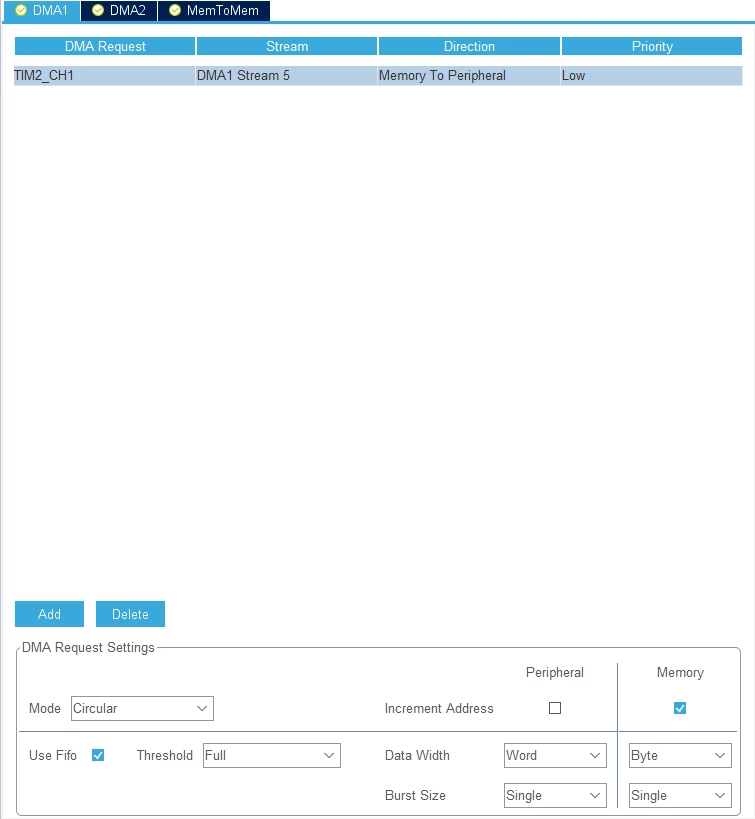
Edit: So after taking a break and thinking about the problem a bit, I think that my led_render, PulseHalfFinishedCallback and PulseFinishedCallback functions need to be adjusted to fit the new DMA Sorry for my misleading first question (if it really wasnt the problem :^) ). Code from the git above inbound:
// LED parameters
#define NUM_BPP (4) // SK6812
#define NUM_PIXELS (8) //number of LEDs controlled for tim1 -> adjust for application needed
#define NUM_BYTES (NUM_BPP * NUM_PIXELS)

// LED color buffer
uint8_t rgb_arr[NUM_BYTES] = {0};//Tim1

// LED write buffer
#define WR_BUF_LEN (NUM_BPP * 8 * 2)//Tim1
uint8_t wr_buf[WR_BUF_LEN] = {0};
uint_fast8_t wr_buf_p = 0;

void led_render() {
 if(wr_buf_p != 0 || hdma_tim1_ch1.State != HAL_DMA_STATE_READY) {
 // Ongoing transfer, cancel!
 for(uint8_t i = 0; i < WR_BUF_LEN; ++i) wr_buf[i] = 0;
 wr_buf_p = 0;
 HAL_TIM_PWM_Stop_DMA(&htim1, TIM_CHANNEL_1);
 return;
 }
 // Ooh boi the first data buffer half (and the second!)
 for(uint_fast8_t i = 0; i < 8; ++i) {
 wr_buf[i ] = PWM_LO << (((rgb_arr[0] << i) & 0x80) > 0);
 wr_buf[i + 8] = PWM_LO << (((rgb_arr[1] << i) & 0x80) > 0);
 wr_buf[i + 16] = PWM_LO << (((rgb_arr[2] << i) & 0x80) > 0);
 wr_buf[i + 24] = PWM_LO << (((rgb_arr[3] << i) & 0x80) > 0);
 wr_buf[i + 32] = PWM_LO << (((rgb_arr[4] << i) & 0x80) > 0);
 wr_buf[i + 40] = PWM_LO << (((rgb_arr[5] << i) & 0x80) > 0);
 wr_buf[i + 48] = PWM_LO << (((rgb_arr[6] << i) & 0x80) > 0);
 wr_buf[i + 56] = PWM_LO << (((rgb_arr[7] << i) & 0x80) > 0);
 }

 HAL_TIM_PWM_Start_DMA(&htim1, TIM_CHANNEL_1, (uint32_t *)wr_buf, WR_BUF_LEN);
 wr_buf_p = 2; // Since we're ready for the next buffer
}

void HAL_TIM_PWM_PulseFinishedHalfCpltCallback(TIM_HandleTypeDef *htim) {
 // DMA buffer set from LED(wr_buf_p) to LED(wr_buf_p + 1)
 if(wr_buf_p < NUM_PIXELS) {
 // We're in. Fill the even buffer
 for(uint_fast8_t i = 0; i < 8; ++i) {
 wr_buf[i ] = PWM_LO << (((rgb_arr[4 * wr_buf_p ] << i) & 0x80) > 0);
 wr_buf[i + 8] = PWM_LO << (((rgb_arr[4 * wr_buf_p + 1] << i) & 0x80) > 0);
 wr_buf[i + 16] = PWM_LO << (((rgb_arr[4 * wr_buf_p + 2] << i) & 0x80) > 0);
 wr_buf[i + 24] = PWM_LO << (((rgb_arr[4 * wr_buf_p + 3] << i) & 0x80) > 0);
 }
 wr_buf_p++;
 } else if (wr_buf_p < NUM_PIXELS + 2) {
 // Last two transfers are resets. SK6812: 64 * 1.25 us = 80 us == good enough reset
 // First half reset zero fill
 for(uint8_t i = 0; i < WR_BUF_LEN / 2; ++i) wr_buf[i] = 0;
 wr_buf_p++;
 }
}

void HAL_TIM_PWM_PulseFinishedCallback(TIM_HandleTypeDef *htim) {
 // DMA buffer set from LED(wr_buf_p) to LED(wr_buf_p + 1)
 if(wr_buf_p < NUM_PIXELS) {
 // We're in. Fill the odd buffer
 for(uint_fast8_t i = 0; i < 8; ++i) {
 wr_buf[i + 32] = PWM_LO << (((rgb_arr[4 * wr_buf_p ] << i) & 0x80) > 0);
 wr_buf[i + 40] = PWM_LO << (((rgb_arr[4 * wr_buf_p + 1] << i) & 0x80) > 0);
 wr_buf[i + 48] = PWM_LO << (((rgb_arr[4 * wr_buf_p + 2] << i) & 0x80) > 0);
 wr_buf[i + 56] = PWM_LO << (((rgb_arr[4 * wr_buf_p + 3] << i) & 0x80) > 0);
 }
 wr_buf_p++;
 } else if (wr_buf_p < NUM_PIXELS + 2) {
 // Second half reset zero fill
 for(uint8_t i = WR_BUF_LEN / 2; i < WR_BUF_LEN; ++i) wr_buf[i] = 0;
 ++wr_buf_p;
 } else {
 // We're done. Lean back and until next time!
 wr_buf_p = 0;
 HAL_TIM_PWM_Stop_DMA(&htim2, TIM_CHANNEL_1);
 }
}
Any help on what changes need to be made , whether with CubeMX or via coding, are much appreciated!
