Turn on suggestions
Auto-suggest helps you quickly narrow down your search results by suggesting possible matches as you type.
Showing results for
- STMicroelectronics Community
- STM32 MCUs
- STM32 MCUs Wireless
- Re: Not Receiving UART message from STM32WL5M to L...
Options
- Subscribe to RSS Feed
- Mark Topic as New
- Mark Topic as Read
- Float this Topic for Current User
- Bookmark
- Subscribe
- Mute
- Printer Friendly Page
Not Receiving UART message from STM32WL5M to Laptop
Options
- Mark as New
- Bookmark
- Subscribe
- Mute
- Subscribe to RSS Feed
- Permalink
- Email to a Friend
- Report Inappropriate Content
2025-02-11 01:41 AM - last edited on 2025-02-11 06:17 AM by Andrew Neil
Hi there, I have an B-WL5M-SUBG1 evaluation board which uses the STM32WL5M module.
I am having problems with the STM32 receiving a message I am sending it from my laptop via python.
I connect between the stm32 and the laptop via an RS422/485 converter. I've used the converter many times before to read print statements from the stm32.
Here is the stm32 code I am using:
#include "main.h"
#include "stm32wlxx_hal.h"
#include <string.h>
#include <stdio.h>

/* Private variables */
UART_HandleTypeDef huart2;
uint8_t rx_buffer[4];  // Buffer for received data
volatile uint8_t data_received = 0; // Flag for data reception

/* Function prototypes */
void SystemClock_Config(void);
static void MX_GPIO_Init(void);
static void MX_USART2_UART_Init(void);
void Error_Handler(void);
void check_uart_errors(void);

int main(void)
{
    uint8_t tx_ready[] = "READY\r\n";

    /* Initialize system */
    HAL_Init();
    SystemClock_Config();
    MX_GPIO_Init();

    /* Reset UART2 before use */
    __HAL_RCC_USART2_FORCE_RESET();
    HAL_Delay(10);
    __HAL_RCC_USART2_RELEASE_RESET();

    MX_USART2_UART_Init();

    /* Transmit READY message */
    if (HAL_UART_Transmit(&huart2, tx_ready, sizeof(tx_ready) - 1, 300) != HAL_OK)
    {
        Error_Handler();
    }

    HAL_Delay(10); // Prevent issues

    /* Clear UART RX buffer and start receiving */
    __HAL_UART_FLUSH_DRREGISTER(&huart2);
    memset(rx_buffer, 0, sizeof(rx_buffer));

    if (HAL_UART_Receive_IT(&huart2, rx_buffer, sizeof(rx_buffer)) != HAL_OK)
    {
        Error_Handler();
    }

    while (1)
    {
        if (data_received)
        {
            data_received = 0; // Reset flag

            /* Debug: Print received bytes */
            char debug_msg[50];
            sprintf(debug_msg, "RX CALLBACK: %02X %02X %02X %02X\r\n",
                    rx_buffer[0], rx_buffer[1], rx_buffer[2], rx_buffer[3]);
            HAL_UART_Transmit(&huart2, (uint8_t *)debug_msg, strlen(debug_msg), 300);
            HAL_Delay(10);

            /* Echo back the received 4 bytes */
            if (HAL_UART_Transmit(&huart2, rx_buffer, 4, 300) != HAL_OK)
            {
                Error_Handler();
            }

            /* Restart reception */
            memset(rx_buffer, 0, sizeof(rx_buffer));
            if (HAL_UART_Receive_IT(&huart2, rx_buffer, sizeof(rx_buffer)) != HAL_OK)
            {
                Error_Handler();
            }

            check_uart_errors(); // Check for errors after transmission
        }
    }
}

/**
  * @brief System Clock Configuration
  */
void SystemClock_Config(void)
{
    RCC_OscInitTypeDef RCC_OscInitStruct = {0};
    RCC_ClkInitTypeDef RCC_ClkInitStruct = {0};

    __HAL_PWR_VOLTAGESCALING_CONFIG(PWR_REGULATOR_VOLTAGE_SCALE2);
    RCC_OscInitStruct.OscillatorType = RCC_OSCILLATORTYPE_MSI;
    RCC_OscInitStruct.MSIState = RCC_MSI_ON;
    RCC_OscInitStruct.MSICalibrationValue = RCC_MSICALIBRATION_DEFAULT;
    RCC_OscInitStruct.MSIClockRange = RCC_MSIRANGE_6;  // 4 MHz
    RCC_OscInitStruct.PLL.PLLState = RCC_PLL_NONE;
    if (HAL_RCC_OscConfig(&RCC_OscInitStruct) != HAL_OK)
    {
        Error_Handler();
    }
    RCC_ClkInitStruct.ClockType = RCC_CLOCKTYPE_HCLK | RCC_CLOCKTYPE_SYSCLK |
                                  RCC_CLOCKTYPE_PCLK1 | RCC_CLOCKTYPE_PCLK2;
    RCC_ClkInitStruct.SYSCLKSource = RCC_SYSCLKSOURCE_MSI;
    RCC_ClkInitStruct.AHBCLKDivider = RCC_SYSCLK_DIV1;
    RCC_ClkInitStruct.APB1CLKDivider = RCC_HCLK_DIV1;
    RCC_ClkInitStruct.APB2CLKDivider = RCC_HCLK_DIV1;
    if (HAL_RCC_ClockConfig(&RCC_ClkInitStruct, FLASH_LATENCY_0) != HAL_OK)
    {
        Error_Handler();
    }
}

/**
  * @brief USART2 Initialization Function
  */
static void MX_USART2_UART_Init(void)
{
    huart2.Instance = USART2;
    huart2.Init.BaudRate = 115200;
    huart2.Init.WordLength = UART_WORDLENGTH_8B;
    huart2.Init.StopBits = UART_STOPBITS_1;
    huart2.Init.Parity = UART_PARITY_NONE;
    huart2.Init.Mode = UART_MODE_TX_RX;
    huart2.Init.HwFlowCtl = UART_HWCONTROL_NONE;
    huart2.Init.OverSampling = UART_OVERSAMPLING_16;
    huart2.Init.OneBitSampling = UART_ONE_BIT_SAMPLE_DISABLE;
    huart2.Init.ClockPrescaler = UART_PRESCALER_DIV1;
    huart2.AdvancedInit.AdvFeatureInit = UART_ADVFEATURE_NO_INIT;
    if (HAL_UART_Init(&huart2) != HAL_OK)
    {
        Error_Handler();
    }
}

/**
  * @brief UART RX Complete Callback
  */
void HAL_UART_RxCpltCallback(UART_HandleTypeDef *huart)
{
    if (huart->Instance == USART2)
    {
        data_received = 1; // Set flag to process received data
    }
}

/**
  * @brief Check UART Errors
  */
void check_uart_errors(void)
{
    uint32_t error = HAL_UART_GetError(&huart2);
    if (error != HAL_UART_ERROR_NONE)
    {
        char error_msg[50];
        sprintf(error_msg, "UART ERROR: 0x%lX\r\n", error);
        HAL_UART_Transmit(&huart2, (uint8_t *)error_msg, strlen(error_msg), 300);
    }
}

/**
  * @brief GPIO Initialization Function
  */
static void MX_GPIO_Init(void)
{
    __HAL_RCC_GPIOA_CLK_ENABLE();

    GPIO_InitTypeDef GPIO_InitStruct = {0};
    /* Configure PA2 and PA3 as Alternate Function (AF7) for USART2 */
    GPIO_InitStruct.Pin = GPIO_PIN_2 | GPIO_PIN_3;
    GPIO_InitStruct.Mode = GPIO_MODE_AF_PP;
    GPIO_InitStruct.Pull = GPIO_NOPULL;
    GPIO_InitStruct.Speed = GPIO_SPEED_FREQ_LOW;
    GPIO_InitStruct.Alternate = GPIO_AF7_USART2;
    HAL_GPIO_Init(GPIOA, &GPIO_InitStruct);
}

/**
  * @brief  Error Handler.
  */
void Error_Handler(void)
{
    __disable_irq();
    while (1)
    {
    }
}
My python code is this:
#!/usr/bin/env python3
import serial
import time

def main():
    ser = serial.Serial(
        port="COM4",
        baudrate=115200,
        bytesize=8,
        parity='N',
        stopbits=1,
        timeout=2,
        xonxoff=False,
        rtscts=False,
        dsrdtr=False
    )

    print(f"Opened COM4 at {ser.baudrate} baud.")

    # Wait for READY message
    start_time = time.time()
    ready_received = False
    while time.time() - start_time < 5:
        line = ser.readline()
        if line:
            decoded = line.decode(errors="replace")
            print("MCU says:", decoded, end='')
            if "READY" in decoded:
                ready_received = True
                break
    if not ready_received:
        print("No READY message received from MCU.")
        ser.close()
        return

    # Clear UART buffer before sending
    ser.reset_input_buffer()
    time.sleep(0.1)

    # Send 4 bytes
    test_msg = b"DATA"
    print("\nSending:", test_msg)
    ser.write(test_msg)
    ser.flush()

    # Wait for response with timeout
    timeout = time.time() + 5
    while time.time() < timeout:
        line = ser.readline()
        if line.startswith(b"RX CALLBACK: "):
            print("MCU Debug:", line.decode(errors="replace").strip())
            continue
        elif len(line) == 4:
            print("Received:", line)
            break
    else:
        print("Error: No response received from STM32.")

    ser.close()
    print("Done.")

if __name__ == "__main__":
    main()
and my output from python is:
Opened COM4 at 115200 baud.
MCU says: READY

Sending: b'DATA'
Error: No response received from STM32.
Done.
Does anybody have any ideas on what the problem is here and how I could fix it. Any help would be greatly appreciated.
Thank you.
Labels:
- Labels:
-
STM32WL series
-
UART-USART
12 REPLIES 12
Options
- Mark as New
- Bookmark
- Subscribe
- Mute
- Subscribe to RSS Feed
- Permalink
- Email to a Friend
- Report Inappropriate Content
2025-02-11 10:21 AM
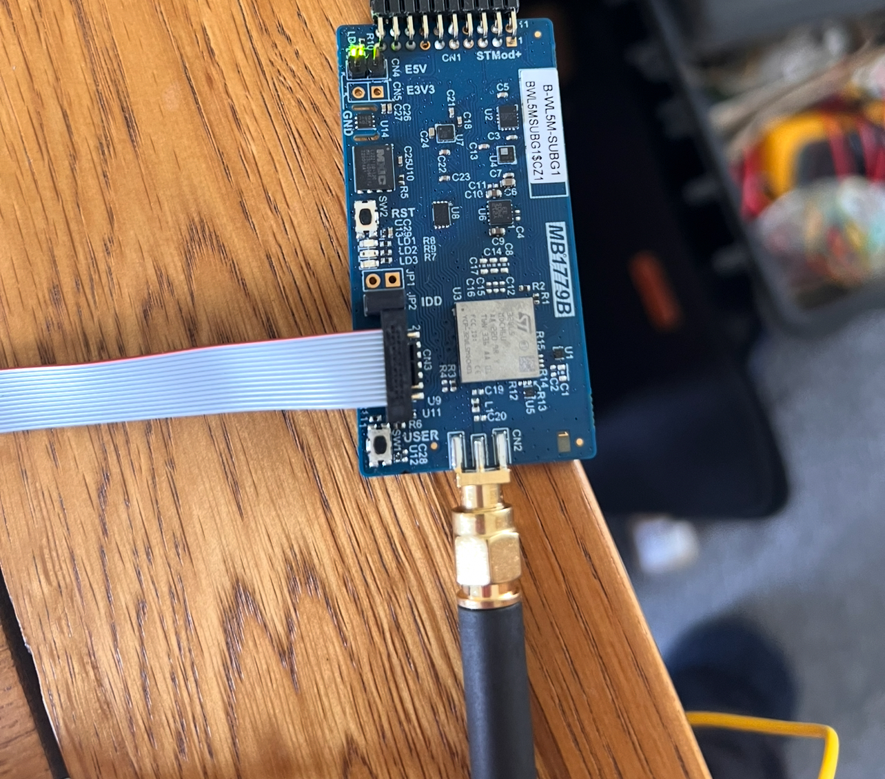
Hi Andrew, I’ll draw a schematic tomorrow. But my setup is as follows:
I have the B-WL5M-SUBG1 powered by a 5V bench PSU.
i connect the B-WL5M-SUBG1 to an MB1440B board to access the tx and rx pins easier.
I connect the Tx and Rx pins to the T+ and T- pins of the converter. I’ve used this setup numerous times to read sensor data from the B-WL5M-SUBG1.
I can the USART2 pins (as usual) set to asynchronous mode.
Pictures below.
Options
- Mark as New
- Bookmark
- Subscribe
- Mute
- Subscribe to RSS Feed
- Permalink
- Email to a Friend
- Report Inappropriate Content
2025-02-11 11:48 PM
Hi Andrew,
There was no particular reason on using the RS422/485 converter other than to see the messages from the STM32 on my Laptop via Putty or my Python program. I've used it in the past on other microcontrollers and used it with the STM32 to view sensor data on my Laptop.
A schematic would show just what I have in the Photos above really.
I've attached the schematic for the B-WL5M-SUBG1, again I am using USART2, which are the Tx and Rx pins on the
Options
- Mark as New
- Bookmark
- Subscribe
- Mute
- Subscribe to RSS Feed
- Permalink
- Email to a Friend
- Report Inappropriate Content
2025-02-12 12:26 AM
- « Previous
-
- 1
- 2
- Next »
Related Content
- Not Receiving UART message from STM32WL5M to Laptop in STM32 MCUs Wireless
- CanBus Communication between Nucleo STM32F446RET and RaspberryPi5 in STM32 MCUs Boards and hardware tools
- Debug autentification with certificate on STM32H563 in STM32 MCUs Security
- L072Z LRWAN1: Switch from Class C to A in STM32 MCUs Wireless
- STM32U585 USBPD Not Working in STM32 MCUs Embedded software