Turn on suggestions
Auto-suggest helps you quickly narrow down your search results by suggesting possible matches as you type.
Showing results for
- STMicroelectronics Community
- STM32 MCUs
- STM32 MCUs Products
- Trying to make a single pulse test.
Options
- Subscribe to RSS Feed
- Mark Topic as New
- Mark Topic as Read
- Float this Topic for Current User
- Bookmark
- Subscribe
- Mute
- Printer Friendly Page
Trying to make a single pulse test.
Options
- Mark as New
- Bookmark
- Subscribe
- Mute
- Subscribe to RSS Feed
- Permalink
- Email to a Friend
- Report Inappropriate Content
2025-11-13 6:41 AM - last edited on 2025-11-13 6:47 AM by mƎALLEm
Hi, I am currently trying to make a single pulse test jig I can use to test MOSFETs in an series resonant converter. I am using the STM32F411CEU6.
I am trying to make a state machine that can make these signals at two different pins. The two variable periods I would like to control with a potentiometer connected to ADC1_IN1 and ADC1_IN2.

However, I only see a high pulse on one of the output and only low on the other. I am trying to use TIM2 as an output compare timing mode where I am using the four different channels and their respective CCRx to toggle the output how I want them. I have tried debugging my code. And it seems like the interrupt fires from the CC1IF but when I am checking in the flag is set it has already been reset and my if sentence won't run. I have attached the code under you would be so kind to take a look.
Thanks
/* USER CODE BEGIN Header */
/**
******************************************************************************
* @file : main.c
* @brief : Main program body
******************************************************************************
* @attention
*
* Copyright (c) 2025 STMicroelectronics.
* All rights reserved.
*
* This software is licensed under terms that can be found in the LICENSE file
* in the root directory of this software component.
* If no LICENSE file comes with this software, it is provided AS-IS.
*
******************************************************************************
*/
/* USER CODE END Header */
/* Includes ------------------------------------------------------------------*/
#include "main.h"
/* Private includes ----------------------------------------------------------*/
/* USER CODE BEGIN Includes */
/* USER CODE END Includes */
/* Private typedef -----------------------------------------------------------*/
/* USER CODE BEGIN PTD */
/* USER CODE END PTD */
/* Private define ------------------------------------------------------------*/
/* USER CODE BEGIN PD */
/* Definer GPIO Pins */
#define OUT1_Pin GPIO_PIN_5
#define OUT1_GPIO_Port GPIOA
#define OUT2_Pin GPIO_PIN_6
#define OUT2_GPIO_Port GPIOA
/* USER CODE END PD */
/* Private macro -------------------------------------------------------------*/
/* USER CODE BEGIN PM */
/* USER CODE END PM */
/* Private variables ---------------------------------------------------------*/
ADC_HandleTypeDef hadc1;
DMA_HandleTypeDef hdma_adc1;
TIM_HandleTypeDef htim2;
/* USER CODE BEGIN PV */
volatile uint16_t adc_dma_buffer[2];
#define ADC_T_ON_INDEX 0 // Index for Channel 1 (T_ON)
#define ADC_T_OFF_INDEX 1 // Index for Channel 2 (T_OFF)
/* USER CODE END PV */
/* Private function prototypes -----------------------------------------------*/
void SystemClock_Config(void);
static void MX_GPIO_Init(void);
static void MX_DMA_Init(void);
static void MX_TIM2_Init(void);
static void MX_ADC1_Init(void);
/* USER CODE BEGIN PFP */
// Antatte funksjoner for å lese ADC-verdier
uint32_t ADC_READING_TO_COUNTS(uint16_t adc_val);
/* USER CODE END PFP */
/* Private user code ---------------------------------------------------------*/
/* USER CODE BEGIN 0 */
// Konverterer 12-bit ADC-verdi (0-4095) til tid i 100ns tellinger.
// Setter f.eks. et tidsområde fra 10us (100 tellinger) til 10ms (100000 tellinger)
uint32_t ADC_READING_TO_COUNTS(uint16_t adc_val) {
const uint32_t MIN_COUNTS = 100; // 10 us
const uint32_t MAX_COUNTS = 200; // 20 us
// Beregner variabel tid innenfor definert område
return (uint32_t)((float)adc_val / 4095.0f * (float)(MAX_COUNTS - MIN_COUNTS)) + MIN_COUNTS;
}
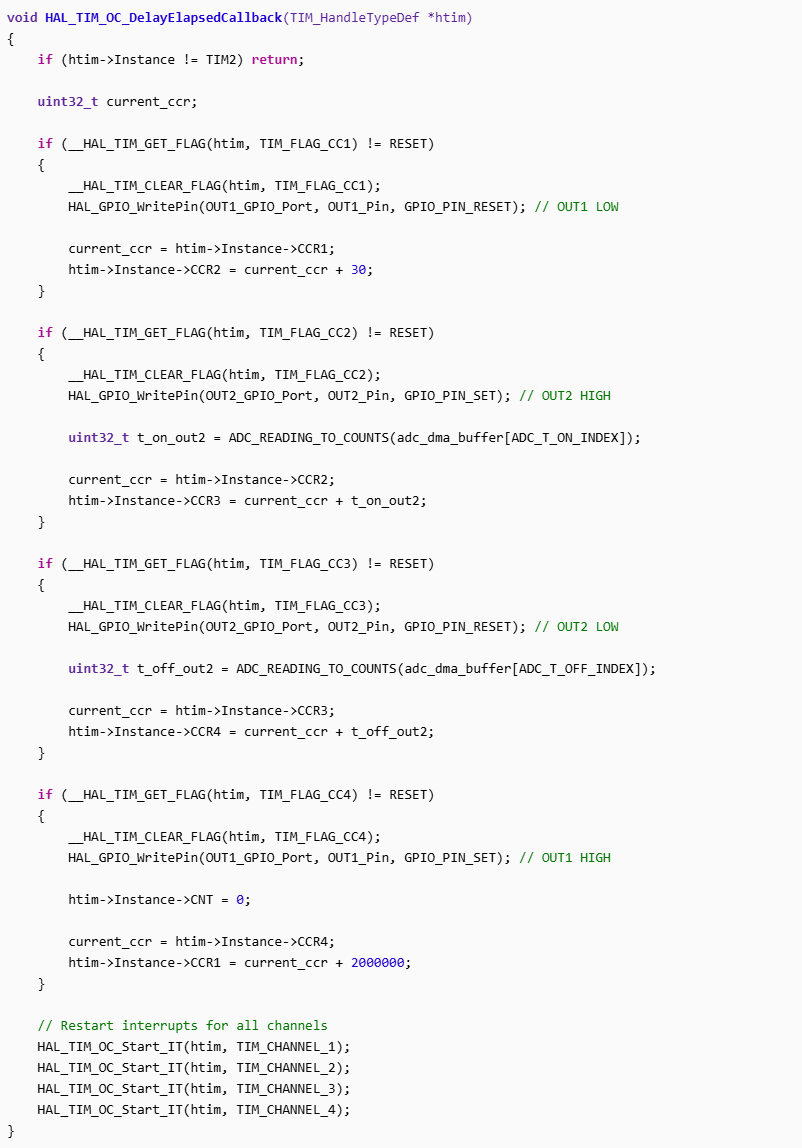
// Implementerer den sekvensielle logikken i Output Compare Callback
void HAL_TIM_OC_DelayElapsedCallback(TIM_HandleTypeDef *htim)
{
if (htim->Instance != TIM2) return;
uint32_t current_ccr;
// --- CCR1: OUT1 LOW (Trinn 1) ---
if (__HAL_TIM_GET_FLAG(htim, TIM_FLAG_CC1) != RESET)
{
__HAL_TIM_CLEAR_FLAG(htim, TIM_FLAG_CC1);
HAL_GPIO_WritePin(OUT1_GPIO_Port, OUT1_Pin, GPIO_PIN_RESET); // OUT1 LAV
// Planlegg CCR2 (OUT2 HIGH) 3us (30 tellinger) senere
current_ccr = htim->Instance->CCR1;
htim->Instance->CCR2 = current_ccr + 30;
}
// --- CCR2: OUT2 HIGH (Trinn 2) ---
else if (__HAL_TIM_GET_FLAG(htim, TIM_FLAG_CC2) != RESET)
{
__HAL_TIM_CLEAR_FLAG(htim, TIM_FLAG_CC2);
HAL_GPIO_WritePin(OUT2_GPIO_Port, OUT2_Pin, GPIO_PIN_SET); // OUT2 HØY
// Les ADC1 for T_ON
uint32_t t_on_out2 = ADC_READING_TO_COUNTS(adc_dma_buffer[ADC_T_ON_INDEX]);
// Planlegg CCR3 (OUT2 LOW)
current_ccr = htim->Instance->CCR2;
htim->Instance->CCR3 = current_ccr + t_on_out2;
}
// --- CCR3: OUT2 LOW (Trinn 3) ---
else if (__HAL_TIM_GET_FLAG(htim, TIM_FLAG_CC3) != RESET)
{
__HAL_TIM_CLEAR_FLAG(htim, TIM_FLAG_CC3);
HAL_GPIO_WritePin(OUT2_GPIO_Port, OUT2_Pin, GPIO_PIN_RESET); // OUT2 LAV
// Les ADC2 for T_OFF
uint32_t t_off_out2 = ADC_READING_TO_COUNTS(adc_dma_buffer[ADC_T_OFF_INDEX]);
// Planlegg CCR4 (OUT1 HIGH)
current_ccr = htim->Instance->CCR3;
htim->Instance->CCR4 = current_ccr + t_off_out2;
}
// --- CCR4: OUT1 HIGH / Syklusstart (Trinn 4) ---
else if (__HAL_TIM_GET_FLAG(htim, TIM_FLAG_CC4) != RESET)
{
__HAL_TIM_CLEAR_FLAG(htim, TIM_FLAG_CC4);
HAL_GPIO_WritePin(OUT1_GPIO_Port, OUT1_Pin, GPIO_PIN_SET); // OUT1 HØY
// *** TILBAKESTILLER CNT ***
htim->Instance->CNT = 0; // Sett telleren til 0 for å starte en ny, frisk syklus.
// *** TILBAKESTILLER CNT ***
// Planlegg CCR1 (OUT1 LOW) 200ms (2,000,000 tellinger) senere
current_ccr = htim->Instance->CCR4;
htim->Instance->CCR1 = current_ccr + 2000000;
}
// For å sikre at interruptene fortsetter å trigge, må vi alltid aktivere de på nytt
HAL_TIM_OC_Start_IT(htim, TIM_CHANNEL_1);
HAL_TIM_OC_Start_IT(htim, TIM_CHANNEL_2);
HAL_TIM_OC_Start_IT(htim, TIM_CHANNEL_3);
HAL_TIM_OC_Start_IT(htim, TIM_CHANNEL_4);
}
/* USER CODE END 0 */
/**
* @brief The application entry point.
* @retval int
*/
int main(void)
{
/* USER CODE BEGIN 1 */
/* USER CODE END 1 */
/* MCU Configuration--------------------------------------------------------*/
/* Reset of all peripherals, Initializes the Flash interface and the Systick. */
HAL_Init();
/* USER CODE BEGIN Init */
/* USER CODE END Init */
/* Configure the system clock */
SystemClock_Config();
/* USER CODE BEGIN SysInit */
/* USER CODE END SysInit */
/* Initialize all configured peripherals */
MX_GPIO_Init();
MX_DMA_Init();
MX_TIM2_Init();
MX_ADC1_Init();
/* USER CODE BEGIN 2 */
// --- START ADC DMA HER! ---
// Starter DMA for kontinuerlig overføring av 2 ADC-verdier til bufferet.
HAL_ADC_Start_DMA(&hadc1, (uint32_t*)adc_dma_buffer, 2);
// --- Initier sekvensen (Trinn 0) ---
HAL_GPIO_WritePin(OUT1_GPIO_Port, OUT1_Pin, GPIO_PIN_SET); // OUT1 HIGH (Start)
// Start TIM2 Base Timer
HAL_TIM_Base_Start(&htim2);
// Sett første hendelse (CCR1) til å trigge 200ms fra nå.
uint32_t initial_cnt = __HAL_TIM_GET_COUNTER(&htim2);
htim2.Instance->CCR1 = initial_cnt + 2000000;
// Aktiver interrupt for CCR1 for å starte løkken
HAL_TIM_OC_Start_IT(&htim2, TIM_CHANNEL_1);
// htim2.Instance->CNT = 0; // Tvinger CNT til 0
/* USER CODE END 2 */
/* Infinite loop */
/* USER CODE BEGIN WHILE */
while (1)
{
/* USER CODE END WHILE */
/* USER CODE BEGIN 3 */
}
/* USER CODE END 3 */
}
/**
* @brief System Clock Configuration
* @retval None
*/
void SystemClock_Config(void)
{
RCC_OscInitTypeDef RCC_OscInitStruct = {0};
RCC_ClkInitTypeDef RCC_ClkInitStruct = {0};
/** Configure the main internal regulator output voltage
*/
__HAL_RCC_PWR_CLK_ENABLE();
__HAL_PWR_VOLTAGESCALING_CONFIG(PWR_REGULATOR_VOLTAGE_SCALE1);
/** Initializes the RCC Oscillators according to the specified parameters
* in the RCC_OscInitTypeDef structure.
*/
RCC_OscInitStruct.OscillatorType = RCC_OSCILLATORTYPE_HSE;
RCC_OscInitStruct.HSEState = RCC_HSE_ON;
RCC_OscInitStruct.PLL.PLLState = RCC_PLL_ON;
RCC_OscInitStruct.PLL.PLLSource = RCC_PLLSOURCE_HSE;
RCC_OscInitStruct.PLL.PLLM = 12;
RCC_OscInitStruct.PLL.PLLN = 96;
RCC_OscInitStruct.PLL.PLLP = RCC_PLLP_DIV2;
RCC_OscInitStruct.PLL.PLLQ = 4;
if (HAL_RCC_OscConfig(&RCC_OscInitStruct) != HAL_OK)
{
Error_Handler();
}
/** Initializes the CPU, AHB and APB buses clocks
*/
RCC_ClkInitStruct.ClockType = RCC_CLOCKTYPE_HCLK|RCC_CLOCKTYPE_SYSCLK
|RCC_CLOCKTYPE_PCLK1|RCC_CLOCKTYPE_PCLK2;
RCC_ClkInitStruct.SYSCLKSource = RCC_SYSCLKSOURCE_PLLCLK;
RCC_ClkInitStruct.AHBCLKDivider = RCC_SYSCLK_DIV1;
RCC_ClkInitStruct.APB1CLKDivider = RCC_HCLK_DIV2;
RCC_ClkInitStruct.APB2CLKDivider = RCC_HCLK_DIV1;
if (HAL_RCC_ClockConfig(&RCC_ClkInitStruct, FLASH_LATENCY_3) != HAL_OK)
{
Error_Handler();
}
}
/**
* @brief ADC1 Initialization Function
* None
* @retval None
*/
static void MX_ADC1_Init(void)
{
/* USER CODE BEGIN ADC1_Init 0 */
/* USER CODE END ADC1_Init 0 */
ADC_ChannelConfTypeDef sConfig = {0};
/* USER CODE BEGIN ADC1_Init 1 */
/* USER CODE END ADC1_Init 1 */
/** Configure the global features of the ADC (Clock, Resolution, Data Alignment and number of conversion)
*/
hadc1.Instance = ADC1;
hadc1.Init.ClockPrescaler = ADC_CLOCK_SYNC_PCLK_DIV4;
hadc1.Init.Resolution = ADC_RESOLUTION_12B;
hadc1.Init.ScanConvMode = ENABLE;
hadc1.Init.ContinuousConvMode = ENABLE;
hadc1.Init.DiscontinuousConvMode = DISABLE;
hadc1.Init.ExternalTrigConvEdge = ADC_EXTERNALTRIGCONVEDGE_NONE;
hadc1.Init.ExternalTrigConv = ADC_SOFTWARE_START;
hadc1.Init.DataAlign = ADC_DATAALIGN_RIGHT;
hadc1.Init.NbrOfConversion = 2;
hadc1.Init.DMAContinuousRequests = ENABLE;
hadc1.Init.EOCSelection = ADC_EOC_SEQ_CONV;
if (HAL_ADC_Init(&hadc1) != HAL_OK)
{
Error_Handler();
}
/** Configure for the selected ADC regular channel its corresponding rank in the sequencer and its sample time.
*/
sConfig.Channel = ADC_CHANNEL_1;
sConfig.Rank = 1;
sConfig.SamplingTime = ADC_SAMPLETIME_28CYCLES;
if (HAL_ADC_ConfigChannel(&hadc1, &sConfig) != HAL_OK)
{
Error_Handler();
}
/** Configure for the selected ADC regular channel its corresponding rank in the sequencer and its sample time.
*/
sConfig.Rank = 2;
if (HAL_ADC_ConfigChannel(&hadc1, &sConfig) != HAL_OK)
{
Error_Handler();
}
/* USER CODE BEGIN ADC1_Init 2 */
/* USER CODE END ADC1_Init 2 */
}
/**
* @brief TIM2 Initialization Function
* None
* @retval None
*/
static void MX_TIM2_Init(void)
{
/* USER CODE BEGIN TIM2_Init 0 */
/* USER CODE END TIM2_Init 0 */
TIM_ClockConfigTypeDef sClockSourceConfig = {0};
TIM_MasterConfigTypeDef sMasterConfig = {0};
TIM_OC_InitTypeDef sConfigOC = {0};
/* USER CODE BEGIN TIM2_Init 1 */
/* USER CODE END TIM2_Init 1 */
htim2.Instance = TIM2;
htim2.Init.Prescaler = 10-1;
htim2.Init.CounterMode = TIM_COUNTERMODE_UP;
htim2.Init.Period = 4294967295;
htim2.Init.ClockDivision = TIM_CLOCKDIVISION_DIV1;
htim2.Init.AutoReloadPreload = TIM_AUTORELOAD_PRELOAD_DISABLE;
if (HAL_TIM_Base_Init(&htim2) != HAL_OK)
{
Error_Handler();
}
sClockSourceConfig.ClockSource = TIM_CLOCKSOURCE_INTERNAL;
if (HAL_TIM_ConfigClockSource(&htim2, &sClockSourceConfig) != HAL_OK)
{
Error_Handler();
}
if (HAL_TIM_OC_Init(&htim2) != HAL_OK)
{
Error_Handler();
}
sMasterConfig.MasterOutputTrigger = TIM_TRGO_RESET;
sMasterConfig.MasterSlaveMode = TIM_MASTERSLAVEMODE_DISABLE;
if (HAL_TIMEx_MasterConfigSynchronization(&htim2, &sMasterConfig) != HAL_OK)
{
Error_Handler();
}
sConfigOC.OCMode = TIM_OCMODE_TIMING;
sConfigOC.Pulse = 0;
sConfigOC.OCPolarity = TIM_OCPOLARITY_HIGH;
sConfigOC.OCFastMode = TIM_OCFAST_DISABLE;
if (HAL_TIM_OC_ConfigChannel(&htim2, &sConfigOC, TIM_CHANNEL_1) != HAL_OK)
{
Error_Handler();
}
if (HAL_TIM_OC_ConfigChannel(&htim2, &sConfigOC, TIM_CHANNEL_2) != HAL_OK)
{
Error_Handler();
}
if (HAL_TIM_OC_ConfigChannel(&htim2, &sConfigOC, TIM_CHANNEL_3) != HAL_OK)
{
Error_Handler();
}
if (HAL_TIM_OC_ConfigChannel(&htim2, &sConfigOC, TIM_CHANNEL_4) != HAL_OK)
{
Error_Handler();
}
/* USER CODE BEGIN TIM2_Init 2 */
/* USER CODE END TIM2_Init 2 */
}
/**
* Enable DMA controller clock
*/
static void MX_DMA_Init(void)
{
/* DMA controller clock enable */
__HAL_RCC_DMA2_CLK_ENABLE();
/* DMA interrupt init */
/* DMA2_Stream0_IRQn interrupt configuration */
HAL_NVIC_SetPriority(DMA2_Stream0_IRQn, 0, 0);
HAL_NVIC_EnableIRQ(DMA2_Stream0_IRQn);
}
/**
* @brief GPIO Initialization Function
* None
* @retval None
*/
static void MX_GPIO_Init(void)
{
GPIO_InitTypeDef GPIO_InitStruct = {0};
/* USER CODE BEGIN MX_GPIO_Init_1 */
/* USER CODE END MX_GPIO_Init_1 */
/* GPIO Ports Clock Enable */
__HAL_RCC_GPIOH_CLK_ENABLE();
__HAL_RCC_GPIOA_CLK_ENABLE();
/*Configure GPIO pin Output Level */
HAL_GPIO_WritePin(GPIOA, GPIO_PIN_5|GPIO_PIN_6, GPIO_PIN_RESET);
/*Configure GPIO pins : PA5 PA6 */
GPIO_InitStruct.Pin = GPIO_PIN_5|GPIO_PIN_6;
GPIO_InitStruct.Mode = GPIO_MODE_OUTPUT_PP;
GPIO_InitStruct.Pull = GPIO_NOPULL;
GPIO_InitStruct.Speed = GPIO_SPEED_FREQ_HIGH;
HAL_GPIO_Init(GPIOA, &GPIO_InitStruct);
/* USER CODE BEGIN MX_GPIO_Init_2 */
/* USER CODE END MX_GPIO_Init_2 */
}
/* USER CODE BEGIN 4 */
/* USER CODE END 4 */
/**
* @brief This function is executed in case of error occurrence.
* @retval None
*/
void Error_Handler(void)
{
/* USER CODE BEGIN Error_Handler_Debug */
/* User can add his own implementation to report the HAL error return state */
__disable_irq();
while (1)
{
}
/* USER CODE END Error_Handler_Debug */
}
#ifdef USE_FULL_ASSERT
/**
* @brief Reports the name of the source file and the source line number
* where the assert_param error has occurred.
* file: pointer to the source file name
* line: assert_param error line source number
* @retval None
*/
void assert_failed(uint8_t *file, uint32_t line)
{
/* USER CODE BEGIN 6 */
/* User can add his own implementation to report the file name and line number,
ex: printf("Wrong parameters value: file %s on line %d\r\n", file, line) */
/* USER CODE END 6 */
}
#endif /* USE_FULL_ASSERT */
Labels:
- Labels:
-
STM32F4 Series
-
TIM
4 REPLIES 4
Options
- Mark as New
- Bookmark
- Subscribe
- Mute
- Subscribe to RSS Feed
- Permalink
- Email to a Friend
- Report Inappropriate Content
2025-11-13 7:16 AM
Dear @MagnusNTNU ,
Thank you for the detailed description and the code. Your approach using TIM2 output compare channels and ADC inputs for variable timing is good, but the issue with only one output toggling and the interrupt flags being cleared before your if checks likely comes from the way the interrupt flags are handled and the logic in your callback.
In your HAL_TIM_OC_DelayElapsedCallback you check the flags sequentially with if ... else if ... else if. However, the interrupt flags for multiple channels can be set simultaneously or very close in time, and the first if that matches clears the flag, so the subsequent checks never see their flags set.
Recommended fix:
- Check and clear the flags for all channels independently, not using else if.
- This ensures that if multiple channels triggered, you handle all their events.
Additional Debugging Tips
- Add debug output (e.g., toggle another GPIO or send UART message) inside each CCR flag handler to confirm all stages are reached.
- Check the timer interrupt priority and ensure no other interrupts block it.
- Verify your GPIO pins are connected correctly and no hardware issues.
Best regards,
Aime
Options
- Mark as New
- Bookmark
- Subscribe
- Mute
- Subscribe to RSS Feed
- Permalink
- Email to a Friend
- Report Inappropriate Content
2025-11-13 7:21 AM
> However, I only see a high pulse on one of the output and only low on the other.
Isn't that consistent with the timing diagram in your post?
Without looking into all details of your code, I would suspect that HAL is probably too slow to cope with µs timings for interrupts. It may be better driving two pins directly by timer channels, say Tim2_Ch1 on PA0 and Tim2_Ch2 on PA1.
You can use output compare in toggle on match mode. The CCR1 and 2 register values detemine the next edge. They can be "auto" updated from an array of values by a circular DMA.
hth
KnarfB
Options
- Mark as New
- Bookmark
- Subscribe
- Mute
- Subscribe to RSS Feed
- Permalink
- Email to a Friend
- Report Inappropriate Content
2025-11-14 12:02 AM
@Aime Thanks for the reply, I tried with only IF sentences but still got the same result. I suspect that KnarfB might be right in the fact that HAL is to slow at handling the us interrupts
Options
- Mark as New
- Bookmark
- Subscribe
- Mute
- Subscribe to RSS Feed
- Permalink
- Email to a Friend
- Report Inappropriate Content
2025-11-14 12:31 AM
Hi @MagnusNTNU ,
If that is the case you should try to change the Timer Output Compare Mode as suggested by @KnarfB.
You are using TIM_OCMODE_TIMING which does not toggle pins automatically.
- You manually toggle GPIO pins in the callback, which is fine, but make sure the pins are configured as GPIO outputs (which you do).
- If you want the timer to toggle pins automatically, you could use TIM_OCMODE_TOGGLE and let hardware do the toggling.
Here is a exemple: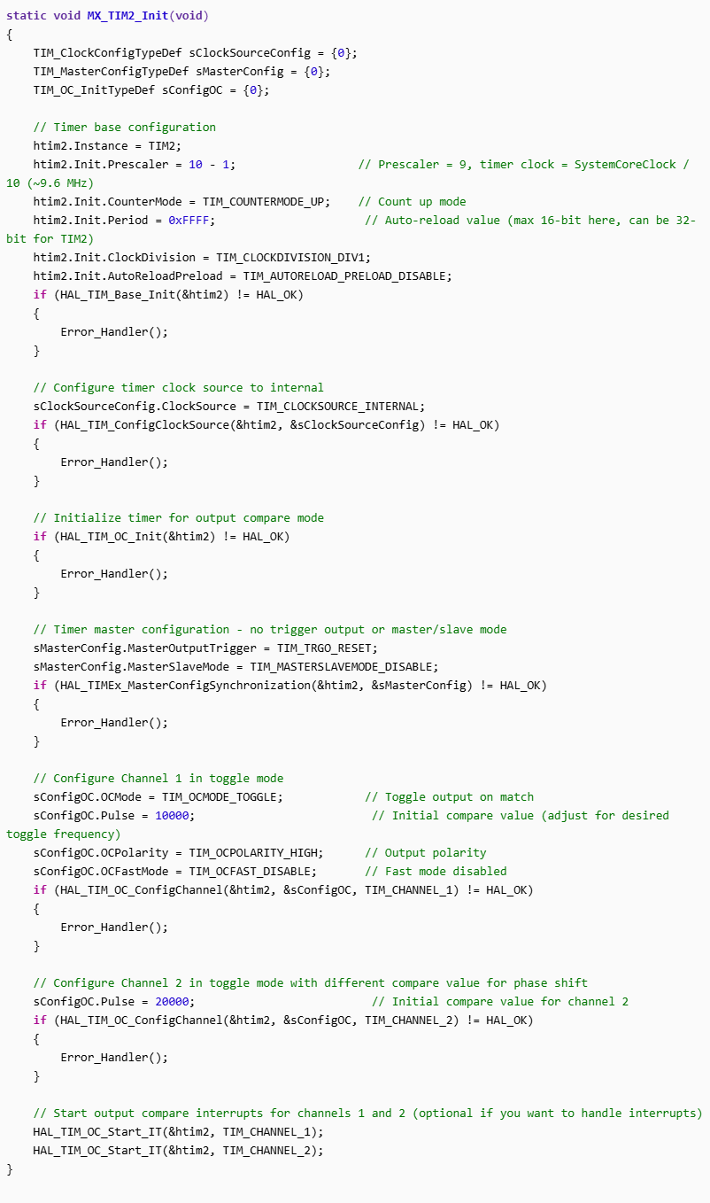
TIM_OCMODE_TOGGLE mode automatically toggles the output pin on each match between the counter and the CCR register.
The Pulse value sets the compare match point — changing it changes the toggle frequency.
You can adjust the CCR values dynamically during runtime using:
Good luck
Aime
Related Content
- Regarding the ADC settings for the EVSPIN32G4 in STM32 MCUs Boards and hardware tools
- ADC EOC wont go down after reading DR in STM32 MCUs Products
- STM32N6 — Target loses connection when hitting breakpoint (LRUN RAM debug, ST-Link) in STM32 MCUs Boards and hardware tools
- Porting LoRaWAN_FUOTA application for STM32WLE5CCU6 in STM32 MCUs Products
- What's the 'proper' way to debug a RUNL application on the STM32N6? in STM32CubeIDE (MCUs)