Turn on suggestions
Auto-suggest helps you quickly narrow down your search results by suggesting possible matches as you type.
Showing results for
- STMicroelectronics Community
- STM32 MCUs
- STM32 MCUs Products
- STM32H743 answers via JTAG but cannot connect
Options
- Subscribe to RSS Feed
- Mark Topic as New
- Mark Topic as Read
- Float this Topic for Current User
- Bookmark
- Subscribe
- Mute
- Printer Friendly Page
STM32H743 answers via JTAG but cannot connect
Options
- Mark as New
- Bookmark
- Subscribe
- Mute
- Subscribe to RSS Feed
- Permalink
- Email to a Friend
- Report Inappropriate Content
2024-02-01 2:04 AM
Hi everybody,
I'm trying to connect to the STM32H743IIT6 on my custom PCB via JTAG. It seems it responds, I traced it with a logic analyzer (attached). I'm not too knowledgeable with JTAG Protocol, but the 0x5253000 the H7 answers seems not to be the chip ID from the BSD file.
Consequently, I cannot connect via STProgrammer or CubeIDE.
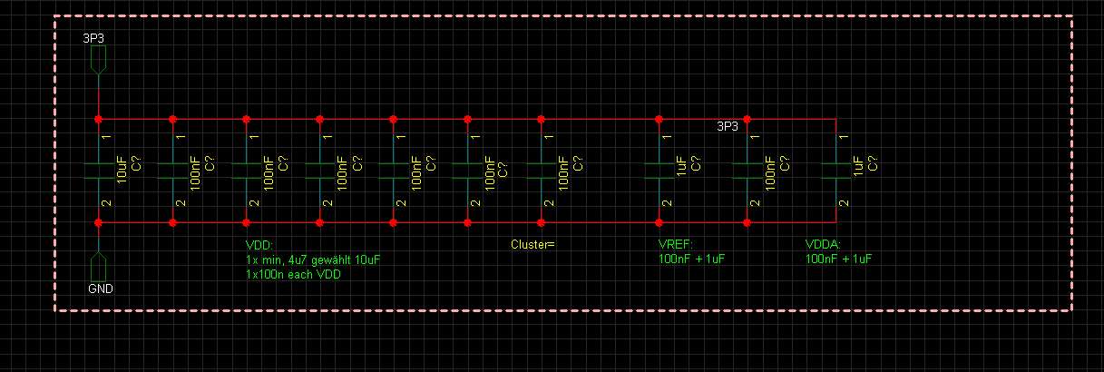
I checked all VDD pins, they're all ok. BOOT0 pin is Ground, NRST is pulled high, VCAP pins are 1V. Pinning is correct.
I tried it with STLINKV3SET and a SEGGER J-Link base with the same results.
I also tried pulling NRST down before flashing with no result and I looked at the signals with an oscilloscope, they seem alright (attached).
Does anyone have an idea? I am out of ideas of what to try. Thanks a lot in advance!
Solved! Go to Solution.
Labels:
- Labels:
-
Flash
-
STM32H7 series
This discussion is locked. Please start a new topic to ask your question.
1 ACCEPTED SOLUTION
Accepted Solutions
Options
- Mark as New
- Bookmark
- Subscribe
- Mute
- Subscribe to RSS Feed
- Permalink
- Email to a Friend
- Report Inappropriate Content
2024-02-01 8:06 PM
Questions (based on experience to have my ST-LINK debug working on a custom STM32U5xx board):
- what is the error message displayed by the debugger tool?
- do you provide MCU VDD on debugger pin - so that debugger can "see" what the core voltage is?
(very important to do - otherwise not correct signal level on debug signals) - do you have this "identification resistor" (for me 100R to GND on a debug header pin) - so that debugger can see it is connected to target board?
- Are you trying as JTAG? Some MCUs, for my understanding, support only SWD (they cannot act and change mode on/from JTAG) - do you force SWD?
- Try to lower the SWD frequency...
- try options in debugger like "connect in low power mode", "connect under reset"
- is the debugger connector (the pins) correct?
Another option to try is:
if you have USB connected - set BOOT to high and see if you can see the bootloader in STM32CubeProgrammer.
If all this fails: potentially the MCU itself is not properly powered.
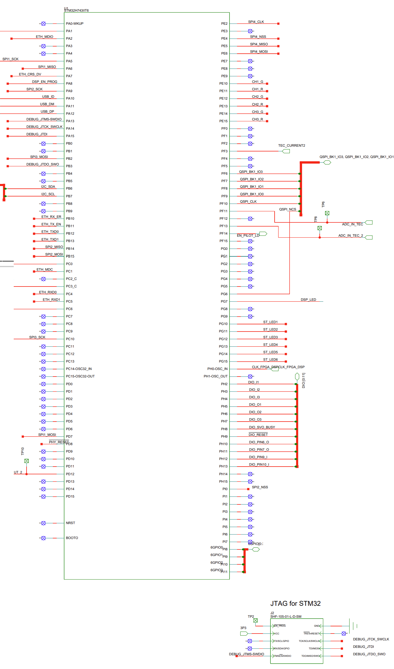
What is the exact wiring of the DEBUG pins on your board (the debugger header connector and its signals)?
6 REPLIES 6
Options
- Mark as New
- Bookmark
- Subscribe
- Mute
- Subscribe to RSS Feed
- Permalink
- Email to a Friend
- Report Inappropriate Content
2024-02-01 2:51 AM
Present Schematic
Would expect VCAP voltage to be closer to 1.25V
LDO or SMPS mode?
Tips, Buy me a coffee, or three.. PayPal Venmo
Up vote any posts that you find helpful, it shows what's working..
Up vote any posts that you find helpful, it shows what's working..
Options
- Mark as New
- Bookmark
- Subscribe
- Mute
- Subscribe to RSS Feed
- Permalink
- Email to a Friend
- Report Inappropriate Content
2024-02-01 4:12 AM
Options
- Mark as New
- Bookmark
- Subscribe
- Mute
- Subscribe to RSS Feed
- Permalink
- Email to a Friend
- Report Inappropriate Content
2024-02-01 9:13 AM
No SMPS on H7 single core.
To give better visibility on the answered topics, please click on "Accept as Solution" on the reply which solved your issue or answered your question.
Options
- Mark as New
- Bookmark
- Subscribe
- Mute
- Subscribe to RSS Feed
- Permalink
- Email to a Friend
- Report Inappropriate Content
2024-02-01 8:06 PM
Questions (based on experience to have my ST-LINK debug working on a custom STM32U5xx board):
- what is the error message displayed by the debugger tool?
- do you provide MCU VDD on debugger pin - so that debugger can "see" what the core voltage is?
(very important to do - otherwise not correct signal level on debug signals) - do you have this "identification resistor" (for me 100R to GND on a debug header pin) - so that debugger can see it is connected to target board?
- Are you trying as JTAG? Some MCUs, for my understanding, support only SWD (they cannot act and change mode on/from JTAG) - do you force SWD?
- Try to lower the SWD frequency...
- try options in debugger like "connect in low power mode", "connect under reset"
- is the debugger connector (the pins) correct?
Another option to try is:
if you have USB connected - set BOOT to high and see if you can see the bootloader in STM32CubeProgrammer.
If all this fails: potentially the MCU itself is not properly powered.
What is the exact wiring of the DEBUG pins on your board (the debugger header connector and its signals)?
Options
- Mark as New
- Bookmark
- Subscribe
- Mute
- Subscribe to RSS Feed
- Permalink
- Email to a Friend
- Report Inappropriate Content
2024-02-01 11:51 PM
Hi everyone,
thanks for the many answers on short notice. Most things you mentioned I considered. Yet again, it was a small problem, which tjaekel post reminded me about.
We use a 10-pin jtag plug on our boards, which is different from the STLINK pinout. The first STLINK pinout you come across on the internet is also a 10-wire, so I build an adapter for it.
The problem is, the STLINK has a 14-pin on the debugger, where a 10-wire flat ribbon is put in the middle, meaning pins 1&2 and 13&14 are NC. I needed to change my adapter to that pinout and flashing with STLINKV3SET worked (see attached and UM2448).
This still doesnt answer why the segger j-link base does not work (pinning there is correct), or why the observed JTAG communication happens - but I can work with the STLINK, so that suffices.


Options
- Mark as New
- Bookmark
- Subscribe
- Mute
- Subscribe to RSS Feed
- Permalink
- Email to a Friend
- Report Inappropriate Content
2024-02-02 2:52 PM
Great, that at least ST-LINK works.
Correct, I had same confusion: NUCLEO boards populate a 2x5 debug header (1.25mm pitch) but ST-LINK adapter has 2x7 pins. I have to "center" the 2x7 ribbon cable as well.
The left and right pin columns are not used. One side is intended to connect the VCP UART to the ST-LINK (coming from a real UART Tx and Rx on MCU, ST-LINK provides these as VCP UART - I do not use).
Here my ST-LINK header.
I went with the same layout as on NUCLEO boards. And I have to "center" the 2x7 ribbon cable.
BTW: on older NUCLEO boards it was possible to "hijack" the ST-LINK on these boards. A NUCLEO board could also act as debugger interface, disconnecting the onboard MCU but connecting another board via the debug header.
On my NUCLEO-U5xx board - this feature seems to be gone.

Announcement
We’re moving the ST Community to a new platform to give you a better and more reliable community experience.
Related Content
- STM32H743 - Setting External Event source for HRTIM Timer in CubeMX ? in STM32CubeMX (MCUs)
- UART Bootloader connection via API in STM32CubeProgrammer (MCUs)
- LAN9353 using STM32H743 in STM32 MCUs Embedded software
- STM32H743 FMC send only part of the data in STM32 MCUs Products
- STM32h755ZI-Q Crashes on a particular code only in STM32 MCUs Products