Turn on suggestions
Auto-suggest helps you quickly narrow down your search results by suggesting possible matches as you type.
Showing results for
- STMicroelectronics Community
- STM32 MCUs
- STM32 MCUs Products
- stm32H7 clock scheme 49.152MHz to 24MHz and max MC...
Options
- Subscribe to RSS Feed
- Mark Topic as New
- Mark Topic as Read
- Float this Topic for Current User
- Bookmark
- Subscribe
- Mute
- Printer Friendly Page
stm32H7 clock scheme 49.152MHz to 24MHz and max MCU
Options
- Mark as New
- Bookmark
- Subscribe
- Mute
- Subscribe to RSS Feed
- Permalink
- Email to a Friend
- Report Inappropriate Content
2024-07-27 11:37 PM
Hello,
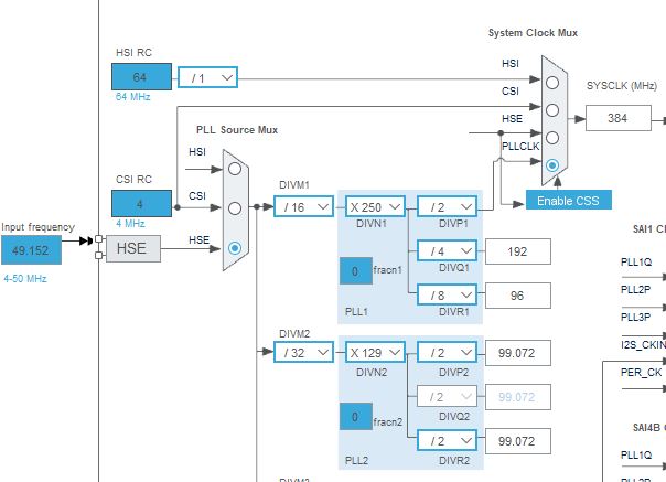
I sort of feel *** not to get sure there not a best solution. I develop an Audio board, with USB HS. I will have a good 49.152MHz clock to drive the SAI, and I wanted to ue it for the HSE.
49.152 * 125 / 256 = 24MHz that I need for the ULPI. Looks good
49.152 * 625 /2 = 480MHz, the max MCU freq. Looks good
I would prefer not use Fracn feature as the above seems to get it right (pure aestetic concern I believe).
But the PLL DIVN1 is limited to 512 for the multiplication factor. So I find as best "solution" 49.152 * 500 /2 = 384MHz... Which wastes some MCU processing power.
Is this the max MCU freq I can acheive while possibly generatind "pure" 24MHz for USB ULPI and not using Fracn? Is there a better solution?
For learning purpose, is there an "algo" to allocate manually PLL M-P-Q to achieve 1 target Freq on PLLQ and max SysCLK?
Sure this is not a pragmatic concern, as Fracn feature allows for 480MHz Sysclk and 24MHz multiples on PLL1Q... I know... (or using an additional 24MHz crystal would make it simple on the clock scheme).
Best regards,
JMF
Labels:
- Labels:
-
RCC
-
STM32H7 Series
4 REPLIES 4
Options
- Mark as New
- Bookmark
- Subscribe
- Mute
- Subscribe to RSS Feed
- Permalink
- Email to a Friend
- Report Inappropriate Content
2024-07-28 01:16 AM - edited 2024-07-28 02:16 AM
Hi,
i would invest more 🙂 and add a 16, 24 or 25 MHz clock - all more easy.
AND 49.xx is anyway out of spec (or on the border of working reliably) :

btw
I made a audio player , for wav, flac, mp3 , from sd-card and usb-stick .
...long story, ... now on H743 and ES9038 DAC as master with its own low jitter clock.
Just - what you building ? and why hi-speed usb ?
+
You need the max. speed 480M really ? I have my cpu at 200M and vos1 , because cpu lifetime... ->
see AN5337 :

vs

If you feel a post has answered your question, please click "Accept as Solution".
Options
- Mark as New
- Bookmark
- Subscribe
- Mute
- Subscribe to RSS Feed
- Permalink
- Email to a Friend
- Report Inappropriate Content
2024-07-28 04:52 AM
About the clock scheme, this is mostly for learning how to do things "OK", and be sure I don't miss something usefull in the way to proceed.
I had read in the documentation (datasheet and RM) that HSE had to be below 50MHz. You are right that CubeMX takes a small margig, certainly with a reason.
About the application:
This is intended to be open harware USB to I2S 8 channels (or more) bridge.This needs USB HS for that number of channels, 24-32 bits depth, Sampling Frequencies in the 96-196kHz range.
I did some experiments on a stm37F7 discovery boards, with the USBX and ThreadX stacks. Seems that the 280MHz has not that much headroom (To be confirmed, and code not optimized). So intention is to have more headroom there. And it could allow for some DSP code in the bridge if interesting.
Thanks for the information on impact of operation mode the lifetime. I was not aware and it is important.
JMF
Options
- Mark as New
- Bookmark
- Subscribe
- Mute
- Subscribe to RSS Feed
- Permalink
- Email to a Friend
- Report Inappropriate Content
2024-07-28 05:50 AM
So i don't want to stop you from using stm , but if had free choice to decide...
i would look at a teensy4.1 , -> or i.MX RT1060 cpu, cortex M7 , 600MHz , has
2x hi-speed usb ports , High-Speed/Full-Speed/Low-Speed OTG core ,
+ 3x SAI (I2S), each can drive 4 data lines (iirr) .
So all you want on chip ... 🙂
Theres even graphical tool to play... https://manicken.github.io/?info=AudioOutputI2SOct


If you feel a post has answered your question, please click "Accept as Solution".
Options
- Mark as New
- Bookmark
- Subscribe
- Mute
- Subscribe to RSS Feed
- Permalink
- Email to a Friend
- Report Inappropriate Content
2024-07-29 12:25 PM
Thanks for the head up on the Teensy 4.1, the fact that it has USB HS peripheral, exposes I2S supporting TDM. This is almost perfect and I was about to stop my project and continue with the Teensy. There are however few features interesting for USB feedback (using TIM2 counter), and multi channels sync by SAI that may be better with "bare" stm32. I have also already invested time in the stm32 ecosystem.
So I will continue, keeping the Teensy as a Plan B 🙂
Thanks again for having pointed that really intersting option !
JMF
Related Content
- The puzzled about SWPMI of STM32H7 in STM32 MCUs Products
- stm32h743zit6 internal temperature sensor in STM32 MCUs Embedded software
- STM32H7 and USB-C Schematics in STM32 MCUs Products
- STM32H7S problem with debugging application in STM32 MCUs TouchGFX and GUI
- MQTT Client Problem in STM32 MCUs Embedded software