Turn on suggestions
Auto-suggest helps you quickly narrow down your search results by suggesting possible matches as you type.
Showing results for
- STMicroelectronics Community
- STM32 MCUs
- STM32 MCUs Products
- Re: Powering up a 5 volt tolerant external pull up...
Options
- Subscribe to RSS Feed
- Mark Topic as New
- Mark Topic as Read
- Float this Topic for Current User
- Bookmark
- Subscribe
- Mute
- Printer Friendly Page
Powering up a 5 volt tolerant external pull up.
Options
- Mark as New
- Bookmark
- Subscribe
- Mute
- Subscribe to RSS Feed
- Permalink
- Email to a Friend
- Report Inappropriate Content
2021-09-02 02:10 AM
Does anyone have experience with 5V pull ups? do you have to power on the 5V source after the MCU is started?
I'm running a STM32L431CBT6 with external 5 volt 10k pull-ups on the pins PB11,12,13,14,15 and PA1. (all flagged as FT pins)
I've been able to plug it in and power it on and even program the MCU. All of the pins above are in "reset_state". So, as far as I can tell, we are not using any internal pull-ups/downs.
After some time and, perhaps, consecutive plug-ins, the chip seems to burn out.
I've since cut the chip off the board (since its burnt) and replaced with with a 47ohm resistive load and taken a measurement of the startup voltages (see attached image).
The blue line is the 5V rail, which is powering the pull ups.
The red line is the 3.3v LDO powering the MCU.
There is clearly a short time where the GPIO pin goes above the MCU power, and there is also about 1.6ms between the MCU powering on and the GPIO pull-ups getting over 4V.
According to the documentation DS11453 (Rev3) page 86, one should be able to put 2V on a GPIO pin to an unpowered MCU, you just cant put VDD+4V.
In previous designs, we have had an MCU activated a switch that allows the 5V to these pins after the MCU is powered up. In this design we have taken the switch out. However, there are other changes in the design that I'm also looking into, so I'm not convinced that this is the actual problem.
Is anyone aware of a reference design that demonstrates 5volt tolerance.
Solved! Go to Solution.
Labels:
- Labels:
-
STM32L4 Series
1 ACCEPTED SOLUTION
Accepted Solutions
Options
- Mark as New
- Bookmark
- Subscribe
- Mute
- Subscribe to RSS Feed
- Permalink
- Email to a Friend
- Report Inappropriate Content
2021-09-02 02:19 AM
When unpowered (VDD=0), the max on any pin is 4V. So yes, you need to power it before you can apply 5V to a pin, per the datasheet.

But your powerup chart does not violate this condition, so that's probably not the issue.
If you feel a post has answered your question, please click "Accept as Solution".
12 REPLIES 12
Options
- Mark as New
- Bookmark
- Subscribe
- Mute
- Subscribe to RSS Feed
- Permalink
- Email to a Friend
- Report Inappropriate Content
2021-09-02 02:19 AM
When unpowered (VDD=0), the max on any pin is 4V. So yes, you need to power it before you can apply 5V to a pin, per the datasheet.
But your powerup chart does not violate this condition, so that's probably not the issue.
If you feel a post has answered your question, please click "Accept as Solution".
Options
- Mark as New
- Bookmark
- Subscribe
- Mute
- Subscribe to RSS Feed
- Permalink
- Email to a Friend
- Report Inappropriate Content
2021-09-02 02:51 AM
> After some time and, perhaps, consecutive plug-ins, the chip seems to burn out.
What exactly are the symptoms?
> I've since cut the chip off the board (since its burnt)
If you still have that specimen and can expose pins, you may want to check at least the protection diodes from individual pins to ground. It's not a definitive test, but it's cheap and easy and sometimes it reveals a potential problem with heavily abused pins. You can't test whatever positive rail protection there is for the FT pins, but you can test it on the TT pins.
JW
Options
- Mark as New
- Bookmark
- Subscribe
- Mute
- Subscribe to RSS Feed
- Permalink
- Email to a Friend
- Report Inappropriate Content
2021-09-02 02:57 AM
Yes.. that what I thought. Good to have a 2nd opinion on if this violates or not.
Thanks for adding the screen shot too.
The 5V rail is supplied by an buck , which has its own rise time as shown. As far as i can tell its pretty consistent, but there might also be some edge cases that cause a 4+ V before the LDO comes on.
Options
- Mark as New
- Bookmark
- Subscribe
- Mute
- Subscribe to RSS Feed
- Permalink
- Email to a Friend
- Report Inappropriate Content
2021-09-02 05:45 AM
I've burned out two boards, as far as I can tell, they both went dead after connecting them to power a few times. (18V to a buck that then outputs the 5V shown). The boards did, at one point run fine for some hours. So i do suspect strongly a power-up/down issue.
Anyway, the MCU i removed is gone. But I still have it on the 2nd board where i have pulled off the 5V compents and the pull ups.
the resistance across VDD, VSS shows 34 ohms.
A flir camera also verifies something has burned out in the MCU as it gets very hot.
I'm wondering, why cant you test the FT pins like this?
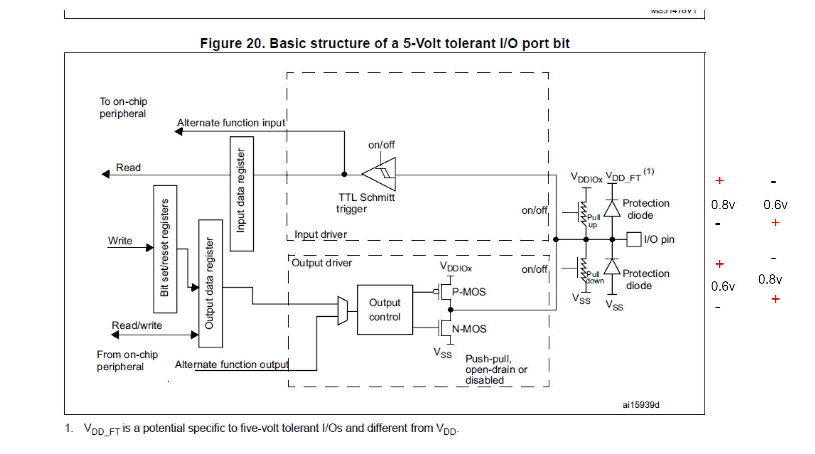
I tried it anyway.
On there I can measure using the diode setting on the multimeter and it shows 0.6 to 0.8 v depending on on the orientation. (see image)
I only have a limited number of MCU's right now (damn chip crisis), so it's better to get at least some early theories before starting the next round of destructive testing in order to have a better idea of what I'm testing for.
Options
- Mark as New
- Bookmark
- Subscribe
- Mute
- Subscribe to RSS Feed
- Permalink
- Email to a Friend
- Report Inappropriate Content
2021-09-02 11:48 AM
> pretty consistent
The consistency might be killing you here. You would need 100% consistency.
Seems very likely powerup is the issue based on your commends. If you could power the LDO off of the 5V rail, that would fix it.
If you feel a post has answered your question, please click "Accept as Solution".
Options
- Mark as New
- Bookmark
- Subscribe
- Mute
- Subscribe to RSS Feed
- Permalink
- Email to a Friend
- Report Inappropriate Content
2021-09-02 03:22 PM
> I'm wondering, why cant you test the FT pins like this?
The protection structure is not published, but imagine it's a Zener with breakdown voltage of around 6V against VSS (ground); but then there are also fine input transistors between the pin and VDD with breakdown voltage of cca 4V. So, if you'd want to measure that Zener while VDD=VSS (i.e. when the circuit is switched off), you would exceed that input transistors breakdown voltage and damage them. Typical diode setting on multimeter won't exceed output voltage of 1V so it won't even get close to the Zener's (or input transistors') breakdown.
Diode setting on multimeter typically sources 1mA, so if between VDD and VSS is 34 ohms (due to internal breakdown i.e. melted structures in the chip), that will result in maximum drop of 34mV - in other words, measuring pin against VSS vs. pin against VDD will result in roughly the same voltage and won't reveal any internal structure.
The idea of measuring the IO pins is, that should a damaging current have flown through the pin, it's likely that it either burned through the input bond, in which case you would measure no diode, or it damaged the protection diodes or the input transistors, in which case you would measure lower voltage than the diodes' against VSS or VDD. So you test all the IO pins, one by one. Would there be one or only a few such pins, you'd then examine the external circuitry associated with those pins. Of course this is no science and there are many other modes of failure which can't be revealed in such simple way, but this is cheap and easy and quick test and usually worth a shot.
JW
Options
- Mark as New
- Bookmark
- Subscribe
- Mute
- Subscribe to RSS Feed
- Permalink
- Email to a Friend
- Report Inappropriate Content
2021-09-02 03:33 PM
The LDO is powered off the 5V rail.
I've started a new round of destructive testing that isolates this specific issue, and its not breaking yet. So I'll get back to you with more info soon.
As far as i can tell though. The FT protection would "probably"* only really cause damage out if it's a prolonged breaking of absolute max ratings. .. or rather, the total energy you put of the protection diode (or whatever is there) has to be great enough to actually heat it and break it. Especially in these lower voltage ranges**.
'* Yes... its quite a big assumption.
**as opposed to ESD in the kV range and breaks it very quickly.
Options
- Mark as New
- Bookmark
- Subscribe
- Mute
- Subscribe to RSS Feed
- Permalink
- Email to a Friend
- Report Inappropriate Content
2021-09-02 03:53 PM
Thanks for all the info. I need to digest this a bit, I've begun new and more conservative tests to ensure that this is in-fact causing the problem.
It would still be of great use if there was some reference application of using a 5V tolerant pin on any STM32. But I need to also spend some more time to search the docs. I'll post it to this question if I find it.
Regarding the protection circuit: I would imaging the protection is more like page 259 from this manual.
However, nowhere else have i found any other mention of Vdd_Ft.
I would imagine that the diode when then be to the standard 3.3v VDD and that the diode would simply be able to just tolerate the constant current at the specified limit. Considering it might be a diode with at least an 0.7 voltage drop between the pin at 5v: that leaves just 1V through the 10k pull up resistor. The result is 0.1mA during normal operation. It also indicates a maximum of 0.5mA in the start up phase (some milli seconds), so I'm thinking it won't really get damaged, and that this is indeed an acceptable way to use the circuit.
And, by extension my issue might be somewhere completely different in my design.
Options
- Mark as New
- Bookmark
- Subscribe
- Mute
- Subscribe to RSS Feed
- Permalink
- Email to a Friend
- Report Inappropriate Content
2021-09-06 08:47 AM
I found here in AN4899 that this is fine to do, but they recommend a zener diode for transient protection.
I have since done a lot of testing an have not been able to break my 3rd board. I'm thinking I must have just done something careless with the first two boards.
None the less, it is still "possible" that this was the issue since I was hot-plugging it a lot causing the possibility of these transients to occur.
I will add this transient protection to my final design.
I am wondering about this resistor. They recommend and what value it should be.
Related Content
- What happens if VBAT is higher than VDD? in STM32 MCUs Boards and hardware tools
- stm32wb5mm-dk external 5V power supply in STM32 MCUs Wireless
- Can't run Code on STM32H743ZI2 without USB ST-LINK Connected in STM32 MCUs Products
- NUCLEO-H533RE E5V external power supply issue in STM32 MCUs Boards and hardware tools
- power voltage detector external input error in code generation with stm32G0 in STM32 MCUs Products