
Associate
September 27, 2024
Solved

Nucleo F746ZG PC13 User Button Triggering Interrupt on Init

  • September 27, 2024
  • 3 replies
  • 2614 views

I have a Nucleo 144-pin F746ZG and I want to configure the user button (PC13, pulled to ground according to MB1137 schematic) to toggle an onboard LED on a falling edge via EXTI interrupt.
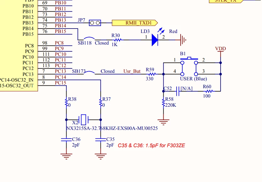
PC13_UserButton.png

I am using this sequence to initialize the interrupt handling:

1) Initialize SYSCFG.

2) Initialize GPIOC Clock.

3) Initialize GPIO registers for PC13, Falling Edge Trigger and Unmask.

4) Initialize SYSCFG_EXTICR, followed by ISER.


An issue I am running into is that on a falling edge it always triggers an interrupt after the initialization is done, even when I pull the pin low via PUPDR. Upon unmasking EXTI_IMR, the EXTI_PR bit is set to 1. If I change the order of the steps the issue goes away, but I doubt I am supposed to do this. What am I overlooking?

 

This topic has been closed for replies.
Best answer by waclawek.jan

By enabling the EXTI interrupt *before* selecting the particular pin/port in SYSCFG.EXTICR you've enabled that interrupt for PA13. That is a debug interface pin, so if you had debugger connected there is enough activity there to trigger the interrupt.

JW

3 replies

jiangfan
ST Employee
September 27, 2024

3) Initialize GPIO registers for PC13, Falling Edge Trigger and Unmask.

4) Initialize SYSCFG_EXTICR, followed by ISER.

I suppose you may clear the interrupt pending bit EXTI_PR before enabling the Falling Edge interrupt to avoid the issue.

JS5Author
Associate
September 27, 2024

Hi jiangfan,

Thank you for getting back to me. I have tried to clear EXTI_PR by explicitly setting it to 1 in a few different places, however it does not take effect and remains at 1. The interrupt is triggered right after NVIC_ISER is set. Once I clear it in the interrupt handler, then it gets updated to 0 as expected.


The issue does not occur if I change the order of initialization to:

1) Initialize SYSCFG.

2) Initialize SYSCFG_EXTICR, followed by ISER.

3) Initialize GPIOC Clock.

4) Initialize GPIO registers for PC13, Falling Edge Trigger and Unmask.


But again, not sure if this is the right thing to do. I haven't seen definitive example of the sequence in Reference Manual or other STM documents.


waclawek.jan
waclawek.janBest answer
Super User
September 28, 2024

By enabling the EXTI interrupt *before* selecting the particular pin/port in SYSCFG.EXTICR you've enabled that interrupt for PA13. That is a debug interface pin, so if you had debugger connected there is enough activity there to trigger the interrupt.

JW